926 Manual V2.0(1J9643) 6/10/99 1:39 PM Page 5
Getting Started
Unpacking
Carefully remove units from packaging. If there is any visible damage, DO NOT attempt to operate the equipment. Notify your dealer or shipping carrier immediately. Keep this guide for future use.
System Contents
• Base Unit
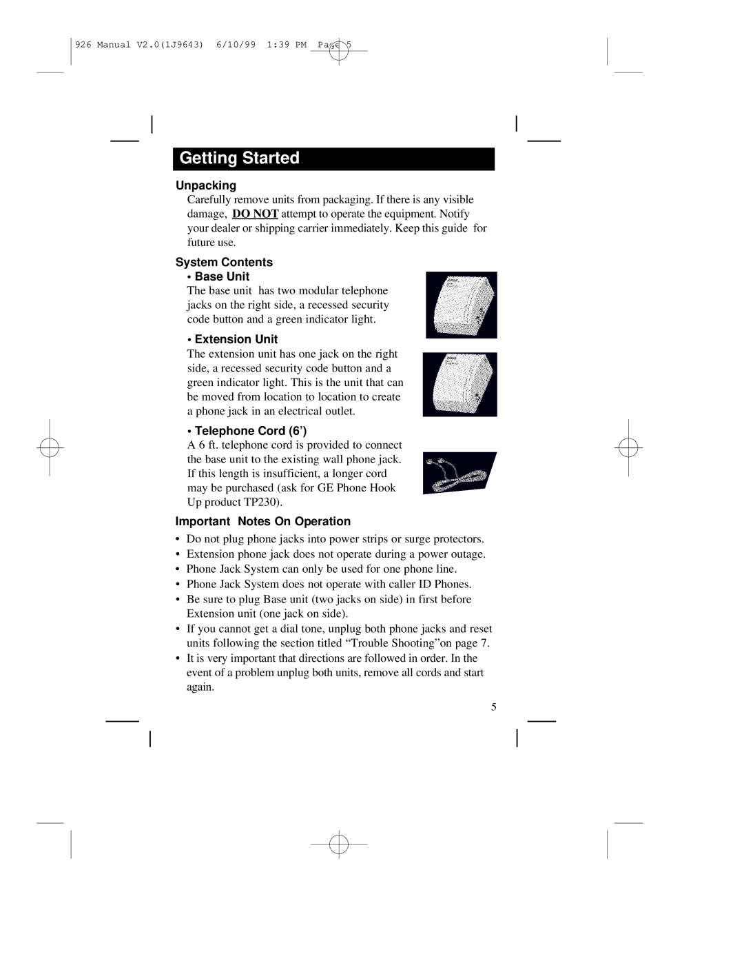
The base unit has two modular telephone jacks on the right side, a recessed security code button and a green indicator light.
• Extension Unit
The extension unit has one jack on the right side, a recessed security code button and a green indicator light. This is the unit that can be moved from location to location to create a phone jack in an electrical outlet.
• Telephone Cord (6’)
A 6 ft. telephone cord is provided to connect the base unit to the existing wall phone jack. If this length is insufficient, a longer cord may be purchased (ask for GE Phone Hook Up product TP230).
Important Notes On Operation
•Do not plug phone jacks into power strips or surge protectors.
•Extension phone jack does not operate during a power outage.
•Phone Jack System can only be used for one phone line.
•Phone Jack System does not operate with caller ID Phones.
•Be sure to plug Base unit (two jacks on side) in first before Extension unit (one jack on side).
•If you cannot get a dial tone, unplug both phone jacks and reset units following the section titled “Trouble Shooting”on page 7.
•It is very important that directions are followed in order. In the event of a problem unplug both units, remove all cords and start again.
5
