Your Acoustic Research Subwoofer delivers powerful, deep bass sound output for a natural, life-like sonic experience. Please follow the direc- tions in this manual to achieve the best performance from your system.
The hook-up and operation of the Subwoofer is the same for a Home Theater surround sound system or a stereo music system. The Subwoofer has its own built-in amplifier, so it works with any sound system. The Subwoofer’s own crossover network sends bass-only signals to the Subwoofer’s built-in amplifier. This lets the Subwoofer add extra bass to the output from your other speakers.
For simplicity, we call your Home Theater system’s or music system’s main speakers the Front speakers. We call your AV receiver, stereo receiver, or integrated amplifier the Receiver.
PLACEMENT
Your Acoustic Research Subwoofer must sit on the floor, in a corner to work properly. The floor and corner are actually a part of the Subwoofer’s design.
Place your Subwoofer in the corner nearest your system’s electronic components to keep wire or cable runs short.
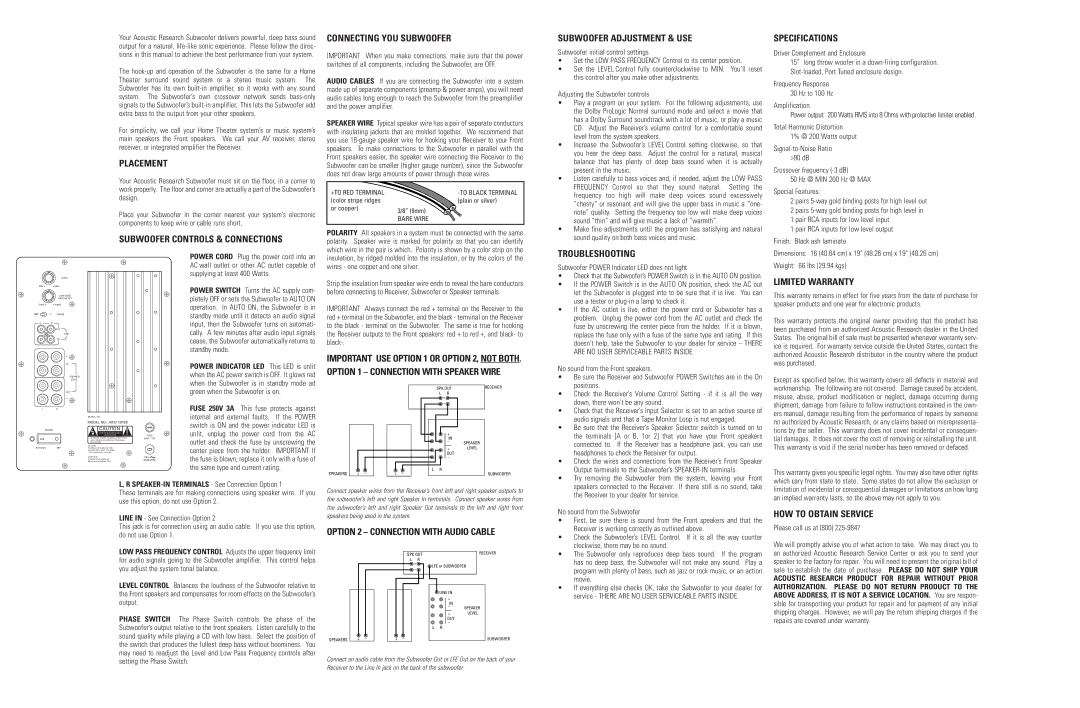
SUBWOOFER CONTROLS & CONNECTIONS
CONNECTING YOU SUBWOOFER
IMPORTANT When you make connections. make sure that the power switches of all components, including the Subwoofer, are OFF.
AUDIO CABLES If you are connecting the Subwoofer into a system made up of separate components (preamp & power amps), you will need audio cables long enough to reach the Subwoofer from the preamplifier and the power amplifier.
SPEAKER WIRE Typical speaker wire has a pair of separate conductors with insulating jackets that are molded together. We recommend that you use 16-gauge speaker wire for hooking your Receiver to your Front speakers. To make connections to the Subwoofer in parallel with the Front speakers easier, the speaker wire connecting the Receiver to the Subwoofer can be smaller (higher gauge number), since the Subwoofer does not draw large amounts of power through these wires.
+TO RED TERMINAL | -TO BLACK TERMINAL |
(color stripe ridges | (plain or silver) |
or cooper) | 3/8” (9mm) |
|
| BARE WIRE |
POLARITY All speakers in a system must be connected with the same polarity. Speaker wire is marked for polarity so that you can identify which wire in the pair is which. Polarity is shown by a color strip on the
SUBWOOFER ADJUSTMENT & USE
Subwoofer initial control settings
•Set the LOW PASS FREQUENCY Control to its center position.
•Set the LEVEL Control fully counterclockwise to MIN. You’ll reset this control after you make other adjustments.
Adjusting the Subwoofer controls
•Play a program on your system. For the following adjustments, use the Dolby ProLogic Normal surround mode and select a movie that has a Dolby Surround soundtrack with a lot of music, or play a music CD. Adjust the Receiver’s volume control for a comfortable sound level from the system speakers.
•Increase the Subwoofer’s LEVEL Control setting clockwise, so that you hear the deep bass. Adjust the control for a natural, musical balance that has plenty of deep bass sound when it is actually present in the music.
•Listen carefully to bass voices and, if needed, adjust the LOW PASS FREQUENCY Control so that they sound natural. Setting the frequency too high will make deep voices sound excessively “chesty” or resonant and will give the upper bass in music a “one- note” quality. Setting the frequency too low will make deep voices sound “thin” and will give music a lack of “warmth”.
•Make fine adjustments until the program has satisfying and natural sound quality on both bass voices and music.
SPECIFICATIONS
Driver Complement and Enclosure
15” long throw woofer in a down-firing configuration. Slot-loaded, Port Tuned enclosure design.
Frequency Response 30 Hz to 100 Hz
Amplification
Power output: 200 Watts RMS into 8 Ohms with protective limiter enabled.
Total Harmonic Distortion 1% @ 200 Watts output
Signal-to-Noise Ratio >90 dB
Crossover frequency (-3 dB)
50 Hz @ MIN 200 Hz @ MAX
Special Features:
2 pairs 5-way gold binding posts for high level out 2 pairs 5-way gold binding posts for high level in 1 pair RCA inputs for low level input
1 pair RCA inputs for low level output
Finish: Black ash laminate
LEVEL
LOW PASS
FREQUENCY
50HZ • | | • 100HZ |
180º | 0º | PHASE |
L R
OUT
LINE
IN
+
IN
-
SPEAKER
LEVEL
-
OUT
+
LR
POWER
SERIAL NO.:
MODEL NO.: ARS115PSB
CAUTION | ! |
RISK OF ELECTRIC SHOCK |
DO NOT OPEN |
WARNING: SHOCK HAZARD-DO NOT OPEN
AVIS: RISQUE DE CHOC ELECTRIQUE-NE PAS OUVRIR
CAUTION:
TO REDUCE THE RISK OF FIRE,
REPLACE WITH ONLY THE SAME
TYPE AND RATING OF FUSE.
ATTENTION:
UTILISER UN FUSIBLE DE
RECHANGE DE MEME TYPE.
FUSE
250V T3A
120V  60HZ 300W
POWER CORD Plug the power cord into an AC wall outlet or other AC outlet capable of supplying at least 400 Watts.
POWER SWITCH Turns the AC supply com- pletely OFF or sets the Subwoofer to AUTO ON operation. In AUTO ON, the Subwoofer is in standby mode until it detects an audio signal input, then the Subwoofer turns on automati- cally. A few minutes after audio input signals cease, the Subwoofer automatically returns to standby mode.
POWER INDICATOR LED This LED is unlit when the AC power switch is OFF. It glows red when the Subwoofer is in standby mode ad green when the Subwoofer is on.
FUSE 250V 3A This fuse protects against internal and external faults. If the POWER switch is ON and the power indicator LED is unlit, unplug the power cord from the AC outlet and check the fuse by unscrewing the center piece from the holder. IMPORTANT If the fuse is blown, replace it only with a fuse of the same type and current rating.
insulation, by ridged molded into the insulation, or by the colors of the wires - one copper and one silver.
Strip the insulation from speaker wire ends to reveal the bare conductors before connecting to Receiver, Subwoofer or Speaker terminals.
IMPORTANT Always connect the red + terminal on the Receiver to the red + terminal on the Subwoofer, and the black - terminal on the Receiver to the black - terminal on the Subwoofer. The same is true for hooking the Receiver outputs to the Front speakers: red + to red +, and black- to black-.
IMPORTANT USE OPTION 1 OR OPTION 2, NOT BOTH. OPTION 1 – CONNECTION WITH SPEAKER WIRE
| | SPK OUT | RECEIVER |
| | L R | |
| | + | |
| | – | |
| | + | |
| | IN | |
| | – | SPEAKER |
| | |
| | + | LEVEL |
| | OUT | |
| | – | |
| + – | L R | |
SPEAKERS | + – | SUBWOOFER |
TROUBLESHOOTING
Subwoofer POWER Indicator LED does not light
•Check that the Subwoofer’s POWER Switch is in the AUTO ON position.
•If the POWER Switch is in the AUTO ON position, check the AC out let the Subwoofer is plugged into to be sure that it is live. You can use a tester or plug-in a lamp to check it.
•If the AC outlet is live, either the power cord or Subwoofer has a problem. Unplug the power cord from the AC outlet and check the fuse by unscrewing the center piece from the holder. If it is blown, replace the fuse only with a fuse of the same type and rating. If this doesn’t help, take the Subwoofer to your dealer for service – THERE ARE NO USER SERVICEABLE PARTS INSIDE.
No sound from the Front speakers.
• | Be sure the Receiver and Subwoofer POWER Switches are in the On |
| positions. |
• | Check the Receiver’s Volume Control Setting - if it is all the way |
| down, there won’t be any sound. |
• | Check that the Receiver’s Input Selector is set to an active source of |
| audio signals and that a Tape Monitor Loop is not engaged. |
• | Be sure that the Receiver’s Speaker Selector switch is turned on to |
| the terminals [A or B, 1or 2] that you have your Front speakers |
| connected to. If the Receiver has a headphone jack, you can use |
| headphones to check the Receiver for output. |
• | Check the wires and connections from the Receiver’s Front Speaker |
| Output terminals to the Subwoofer’s SPEAKER-IN terminals. |
• | Try removing the Subwoofer from the system, leaving your Front |
Dimensions: 16 (40.64 cm) x 19" (48.26 cm) x 19" (48.26 cm)
Weight: 66 lbs (29.94 kgs)
LIMITED WARRANTY
This warranty remains in effect for five years from the date of purchase for speaker products and one year for electronic products.
This warranty protects the original owner providing that the product has been purchased from an authorized Acoustic Research dealer in the United States. The original bill of sale must be presented whenever warranty serv- ice is required. For warranty service outside the United States, contact the authorized Acoustic Research distributor in the country where the product was purchased.
Except as specified below, this warranty covers all defects in material and workmanship. The following are not covered: Damage caused by accident, misuse, abuse, product modification or neglect, damage occurring during shipment, damage from failure to follow instructions contained in the own- ers manual, damage resulting from the performance of repairs by someone no authorized by Acoustic Research, or any claims based on misrepresenta- tions by the seller. This warranty does not cover incidental or consequen- tial damages. It does not cover the cost of removing or reinstalling the unit. This warranty is void if the serial number has been removed or defaced.
This warranty gives you specific legal rights. You may also have other rights which cary from state to state. Some states do not allow the exclusion or
L, R SPEAKER-IN TERMINALS - See Connection Option 1
These terminals are for making connections using speaker wire. If you use this option, do not use Option 2.
LINE IN - See Connection Option 2
This jack is for connection using an audio cable. If you use this option, do not use Option 1.
Connect speaker wires from the Receiver’s front left and right speaker outputs to the subwoofer’s left and right Speaker In terminals. Connect speaker wires from the subwoofer’s left and right Speaker Out terminals to the left and right front speakers being used in the system.
OPTION 2 – CONNECTION WITH AUDIO CABLE
speakers connected to the Receiver. If there still is no sound, take |
the Receiver to your dealer for service. |
No sound from the Subwoofer
• | First, be sure there is sound from the Front speakers and that the |
| Receiver is working correctly as outlined above. |
• | Check the Subwoofer’s LEVEL Control. If it is all the way counter |
limitation of incidental or consequential damages or limitations on how long an implied warranty lasts, so the above may not apply to you.
HOW TO OBTAIN SERVICE
Please call us at (800) 225-9847
LOW PASS FREQUENCY CONTROL Adjusts the upper frequency limit for audio signals going to the Subwoofer amplifier. This control helps you adjust the system tonal balance.
LEVEL CONTROL Balances the loudness of the Subwoofer relative to the Front speakers and compensates for room effects on the Subwoofer’s output.
PHASE SWITCH The Phase Switch controls the phase of the Subwoofer’s output relative to the front speakers. Listen carefully to the sound quality while playing a CD with low bass. Select the position of the switch that produces the fullest deep bass without boominess. You may need to readjust the Level and Low Pass Frequency controls after
RECEIVER
LFE or SUBWOOFER
LINE IN
+
IN
–SPEAKER
+LEVEL
OUT
–
L R
SUBWOOFER
| clockwise, there may be no sound. |
• | The Subwoofer only reproduces deep bass sound. If the program |
| has no deep bass, the Subwoofer will not make any sound. Play a |
| program with plenty of bass, such as jazz or rock music, or an action |
| movie. |
• | If everything else checks OK, take the Subwoofer to your dealer for |
| service - THERE ARE NO USER SERVICEABLE PARTS INSIDE. |
We will promptly advise you of what action to take. We may direct you to an authorized Acoustic Research Service Center or ask you to send your speaker to the factory for repair. You will need to present the original bill of sale to establish the date of purchase. PLEASE DO NOT SHIP YOUR
ACOUSTIC RESEARCH PRODUCT FOR REPAIR WITHOUT PRIOR AUTHORIZATION. PLEASE DO NOT RETURN PRODUCT TO THE ABOVE ADDRESS, IT IS NOT A SERVICE LOCATION. You are respon- sible for transporting your product for repair and for payment of any initial shipping charges. However, we will pay the return shipping charges if the repairs are covered under warranty.