Thank you for choosing a quality
Redring product manufactured in
Peterborough, England
These instructions should be read in full before commencing the installation.
We recommend that the installation should only be carried out by a suitably qualified person.
The Redring WS7 is an open outlet, thermal storage water heater for use with Redring recommended fittings for one outlet only. It operates on the displacement principle i.e.; when cold water is admitted into the bottom of the tank, hot water flows out through the outlet. There are two models: 3kW, which ensures rapid reheating of the water, and a 1kW unit to suit special electrical requirements.
Fixing
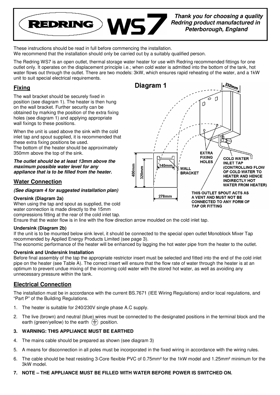
The wall bracket should be securely fixed in position (see diagram 1). The heater is then hung on the wall bracket. Further security can be obtained by marking the position of the extra fixing holes (see diagram 1) and applying appropriate wall fixings to these positions.
When the unit is used above the sink with the cold inlet tap and spout supplied, it is recommended that these extra fixing positions be used.
The bottom of the heater should be approximately 350mm above the top of the sink.
The outlet should be at least 13mm above the maximum possible water level for any appliance that is to be filled from the heater.
Water Connection
(See diagram 4 for suggested installation plan)
Oversink (Diagram 2a)
When using the tap and spout as supplied, the cold water connection is made directly to the 15mm compressions fitting at the rear of the cold inlet tap.
Ensure that the water flow is in line with the flow direction arrow moulded on the cold inlet tap.
Undersink (Diagram 2b)
If the unit is to be mounted below sink level, it should be connected to the special open outlet Monoblock Mixer Tap recommended by Applied Energy Products Limited (see page 3).
The economic performance of the heater will be enhanced by lagging the hot water pipe from the heater to the outlet.
Oversink and Undersink Installation
Before final assembly of the tap the appropriate restrictor insert must be selected and fitted into the end of the cold inlet pipe on the heater (see Table A). The correct insert will ensure that the flow rate of water through the heater is at an optimum to prevent undue mixing of the incoming cold water with the stored hot water, as well as avoiding any unnecessary pressure within the tank.
Electrical Connection
The installation must be in accordance with the current BS.7671 (IEE Wiring Regulations) and/or local regulations, and “Part P” of the Building Regulations.
1.The heater is suitable for 240/230V single phase A.C supply.
2.The live (brown) and neutral (blue) wires must be connected to the designated positions in the terminal block and the
earth (green/yellow) to the earth ![]() position.
position.
3.WARNING: THIS APPLIANCE MUST BE EARTHED
4.The mains cable should be prepared as shown (see diagram 3)
5.A means for disconnection in all poles must be incorporated in the fixed wiring in accordance with the wiring rules.
6.The cable should be heat resisting
7.NOTE – THE APPLIANCE MUST BE FILLED WITH WATER BEFORE POWER IS SWITCHED ON.