32185/32186/32192/32195/32196 Group
Starter Kit User’s Manual M3A-2154G52B
REJ10B0223-0140/Rev.1.40 Jan. 2007 Page 34 of 79
1.1 Outline of the Product
Table 1.1 Mounted Microcomputer Type
Mounted microcomputer type name Evaluation board type name (socket mounted type)
M32192F8VFP Default
M32186F8VFP (Note1) M3A-2154G02A
Note1: Using M32186F8VFP, setting of oscillator circuit should be changed. For details, refer to chapter 2.5 Oscillator
circuit.
Table 1.2 Specification of Product
Operation mode Single-chip mode, Processor mode and External extension mode
Board extension Can be extended using the board’s extension connector
CAN I/F Comes standard with a 2-channel CAN connector, CAN cable included
RS-232C I/F Comes standard with a connector
Serial port One of four channels can be selected using a rotary switch
Analog port Inputs on two channels can be controlled using variable resistor (VR)
controls
Display I/O Comes with a single-port LED
Input I/O Comes with a single-port toggle switch
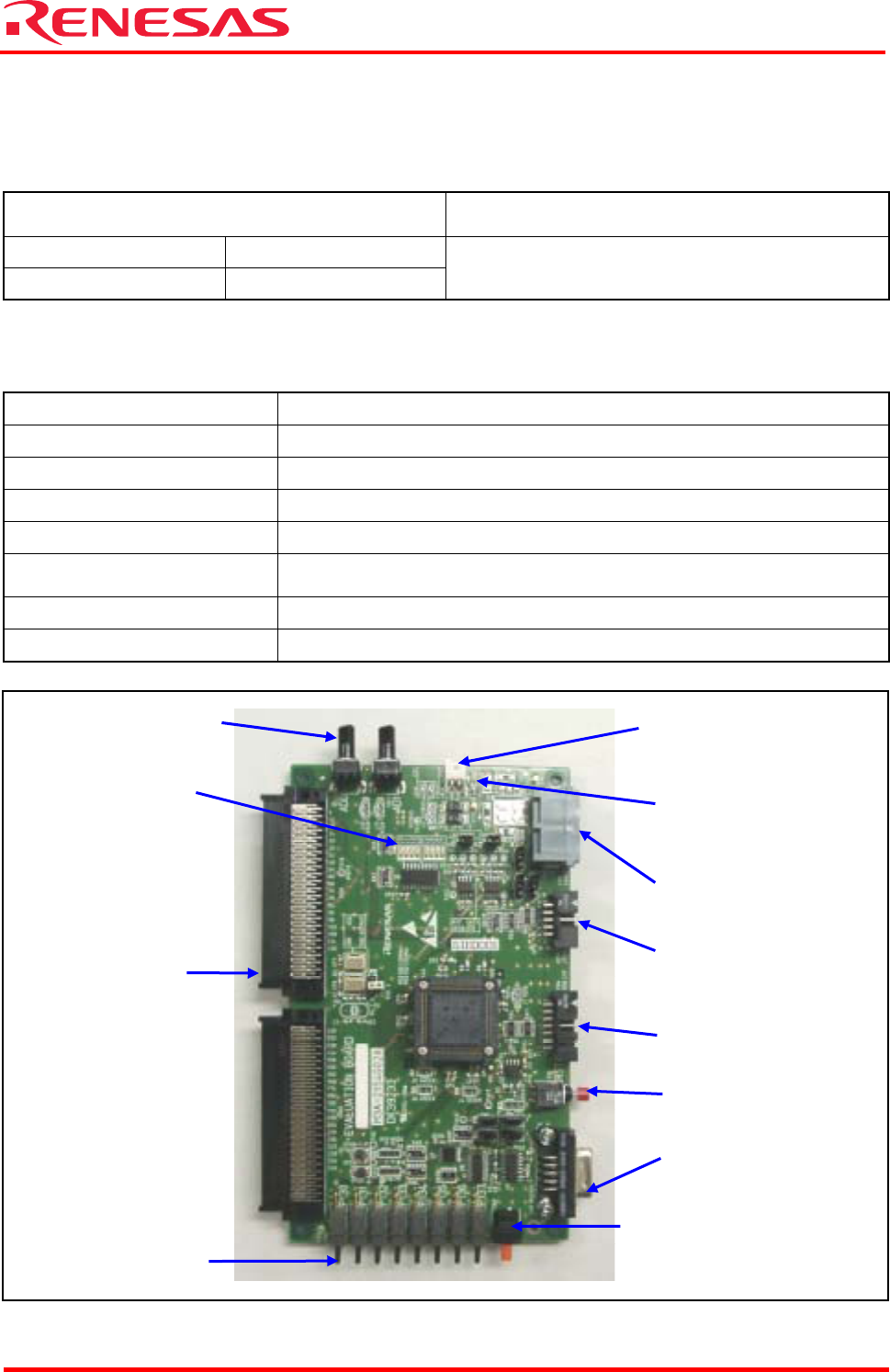
Figure 1.1 Photograph of the M3A-2154G02A
Power supply connector
CAN connector
Reset key
JTAG connector
RS-232C connector
Rotary switch
(selects a serial I/O channel)
Toggle switch
(port input)
External
extension
connector
LED indicator
(port output)
VR controls
LED indicator
(power-on)
NBD connector