OPERATION
SCROLL CUTTING
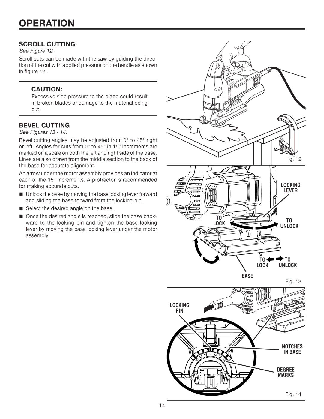
See Figure 12.
Scroll cuts can be made with the saw by guiding the direc- tion of the cut with applied pressure on the handle as shown in figure 12.
CAUTION:
Excessive side pressure to the blade could result in broken blades or damage to the material being cut.
BEVEL CUTTING
See Figures 13 - 14.
Bevel cutting angles may be adjusted from 0° to 45° right or left. Angles for cuts from 0° to 45° in 15° increments are marked on a scale on both the left and right side of the base. Lines are also drawn from the middle section to the back of the base for accurate alignment.
An arrow under the motor assembly provides an indicator at each of the 15° increments. A protractor is recommended for making accurate cuts.
Unlock the base by moving the base locking lever forward and sliding the base forward from the locking pin.
Select the desired angle on the base.
Once the desired angle is reached, slide the base back- ward to the locking pin and tighten the base locking lever by moving the base locking lever under the motor assembly.
Fig. 12
| LOCKING | |
| LEVER | |
TO | TO | |
LOCK | ||
UNLOCK | ||
|
TO ![]()
![]()
![]() TO
TO
LOCK UNLOCK
BASE
Fig. 13
LOCKING
PIN
![]() 45
45
0 3
15
0
15
30![]()
![]() 45
45
NOTCHES
IN BASE
DEGREE
MARKS
Fig. 14
14