OPERATION
BEVEL CUTTING
See Figures 20 - 22.
To make the best possible cut, follow these helpful hints.
Align the line of cut with the inner blade guide notch on the base when making 45° bevel cuts.
Make a trial cut in scrap material along a guideline to determine how much you should offset the guideline on the cutting material.
Adjust the angle of cut to any desired setting between zero and 50°. Positive stops are located at 0°, 45°, and 50°. Refer to To Adjust Bevel Setting later in this manual.
NOTE: Push the positive 50° stop button in while raising the motor housing to set the bevel setting above 45° and up to 50°.
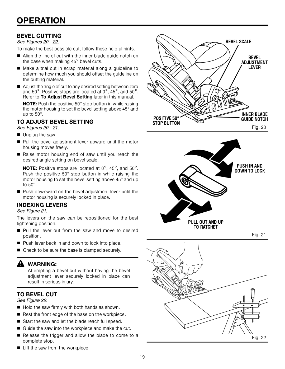
TO ADJUST BEVEL SETTING
See Figures 20 - 21.
Unplug the saw.
Pull the bevel adjustment lever upward until the motor housing moves freely.
Raise motor housing end of saw until you reach the desired angle setting on bevel scale.
NOTE: Positive stops are located at 0°, 45°, and 50°. Push the positive 50° stop button in while raising the
motor housing to set the bevel setting above 45° and up to 50°.
Push downward on the bevel adjustment lever until the motor housing is securely locked in place.
INDEXING LEVERS
See Figure 21.
The levers on the saw can be repositioned for the best tightening position.
Pull the lever out from the saw and move to desired position.
Push lever back in and down to lock into place.
Check to be sure the base is clamped securely.
WARNING:
Attempting a bevel cut without having the bevel adjustment lever securely locked in place can result in serious injury.
TO BEVEL CUT
See Figure 22.
Hold the saw firmly with both hands as shown.
Rest the front edge of the base on the workpiece.
Start the saw and let the blade reach full speed.
Guide the saw into the workpiece and make the cut.
Release the trigger and allow the blade to come to a complete stop.
Lift the saw from the workpiece.
BEVEL SCALE
BEVEL
ADJUSTMENT
LEVER
POSITIVE 50° | INNER BLADE |
GUIDE NOTCH | |
STOP BUTTON | Fig. 20 |
|
PUSH IN AND
DOWN TO LOCK
PULL OUT AND UP
TO RATCHET
Fig. 21
Fig. 22
19