OPERATION
DIRECTION OF ROTATION SELECTOR
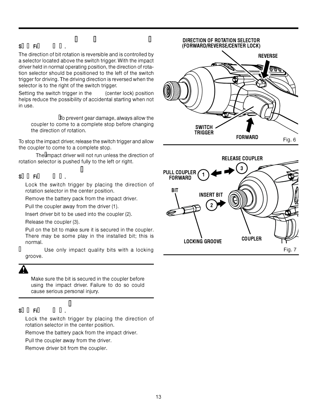
See Figure 6.
The direction of bit rotation is reversible and is controlled by a selector located above the switch trigger. With the impact driver held in normal operating position, the direction of rota- tion selector should be positioned to the left of the switch trigger for driving. The driving direction is reversed when the selector is to the right of the switch trigger.
Setting the switch trigger in the OFF (center lock) position helps reduce the possibility of accidental starting when not in use.
CAUTION: To prevent gear damage, always allow the coupler to come to a complete stop before changing the direction of rotation.
To stop the impact driver, release the switch trigger and allow the coupler to come to a complete stop.
NOTE: The impact driver will not run unless the direction of rotation selector is pushed fully to the left or right.
INSTALLING BITS
See Figure 7.
n Lock the switch trigger by placing the direction of rotation selector in the center position.
nRemove the battery pack from the impact driver.
nPull the coupler away from the driver (1).
nInsert driver bit to be used into the coupler (2).
nRelease the coupler (3).
nPull on the bit to make sure it is secured in the coupler. There may be some play in the installed bit; this is normal.
NOTE: Use only impact quality bits with a locking groove.
![]() WARNING:
WARNING:
Make sure the bit is secured in the coupler before using the impact driver. Failure to do so could cause serious personal injury.
REMOVING BITS
See Figure 7.
n Lock the switch trigger by placing the direction of rotation selector in the center position.
nRemove the battery pack from the impact driver.
nPull the coupler away from the driver.
nRemove driver bit from the coupler.
DIRECTION OF ROTATION SELECTOR (FORWARD/REVERSE/CENTER LOCK)
REVERSE
| SWITCH |
|
| |
| TRIGGER | FORWARD |
| |
|
|
| Fig. 6 | |
|
|
|
| |
|
|
| RELEASE COUPLER |
|
PULL COUPLER | 1 | 3 |
| |
|
| |||
FORWARD |
|
|
| |
|
|
|
| |
BIT |
| INSERT BIT |
| |
|
|
| ||
|
| 2 |
|
|
LOCKING GROOVE | COUPLER |
|
Fig. 7
13