OPERATION
TO INSTALL BATTERY PACK
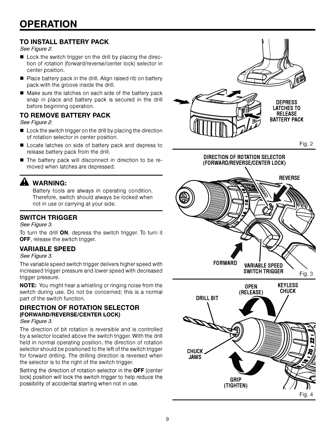
See Figure 2.
Lock the switch trigger on the drill by placing the direc- tion of rotation (forward/reverse/center lock) selector in center position.
Place battery pack in the drill. Align raised rib on battery pack with the groove inside the drill.
Make sure the latches on each side of the battery pack snap in place and battery pack is secured in the drill before beginning operation.
TO REMOVE BATTERY PACK
See Figure 2.
Lock the switch trigger on the drill by placing the direction of rotation selector in center position.
Locate latches on side of battery pack and depress to release battery pack from the drill.
The battery pack will disconnect in direction to be re- moved when latches are depressed.
![]() WARNING:
WARNING:
Battery tools are always in operating condition. Therefore, switch should always be locked when not in use or carrying at your side.
SWITCH TRIGGER
See Figure 3.
To turn the drill ON, depress the switch trigger. To turn it OFF, release the switch trigger.
VARIABLE SPEED
See Figure 3.
The variable speed switch trigger delivers higher speed with increased trigger pressure and lower speed with decreased trigger pressure.
Note: You might hear a whistling or ringing noise from the switch during use. Do not be concerned; this is a normal part of the switch function.
DIRECTION OF ROTATION SELECTOR
(FORWARD/REVERSE/CENTER LOCK)
See Figure 3.
The direction of bit rotation is reversible and is controlled by a selector located above the switch trigger. With the drill held in normal operating position, the direction of rotation selector should be positioned to the left of the switch trigger for forward drilling. The drilling direction is reversed when the selector is to the right of the switch trigger.
Setting the direction of rotation selector in the OFF (center lock) position will lock the switch trigger to help reduce the possibility of accidental starting when not in use.
DEPRESS
LATCHES TO
RELEASE
BATTERY PACK
Fig. 2
DIRECTION OF ROTATION SELECTOR (FORWARD/REVERSE/CENTER LOCK)
REVERSE
FORWARD | VARIABLE SPEED |
|
|
| |
| SWITCH TRIGGER | Fig. 3 |
|
|
OPEN KEYLESS
(RELEASE) CHUCK
DRILL BIT
CHUCK
JAWS
GRIP
(TIGHTEN)
Fig. 4