
8050C specifications
The Ritetemp 8050C is a sophisticated and versatile thermostat designed for residential temperature control, providing users with an array of features that enhance climate management in the home. Known for its user-friendly interface and reliable performance, this thermostat is an excellent choice for homeowners looking to optimize energy efficiency and comfort levels.One of the main features of the Ritetemp 8050C is its programmable capabilities. Users can set tailored schedules for heating and cooling, allowing the thermostat to automatically adjust temperatures based on lifestyle patterns. This feature not only enhances comfort but also helps in reducing energy costs by ensuring that HVAC systems are not running unnecessarily when the home is unoccupied.
The 8050C employs advanced technology, including a large backlit display that ensures ease of reading in various lighting conditions. The intuitive menu navigation allows users to adjust settings effortlessly. Furthermore, the thermostat supports a 7-day programmable schedule, enabling intricate planning that caters to the varying needs of each day throughout the week.
Another noteworthy characteristic of the Ritetemp 8050C is its compatibility with both heating and cooling systems. It works with conventional forced air systems, heat pumps, and even some electric and gas heater configurations. This versatility makes it ideal for a wide range of HVAC applications.
Additionally, the Ritetemp 8050C incorporates a temperature level adjustment feature, allowing users to customize the temperature for both heating and cooling modes. This flexibility ensures that comfort is prioritized, regardless of the external weather conditions.
Energy efficiency is further supported by the built-in adaptive recovery technology. This innovative feature learns how long it takes to reach the programmed temperatures, which minimizes energy consumption while maintaining desired comfort levels. As a result, the thermostat helps homeowners achieve lower utility bills.
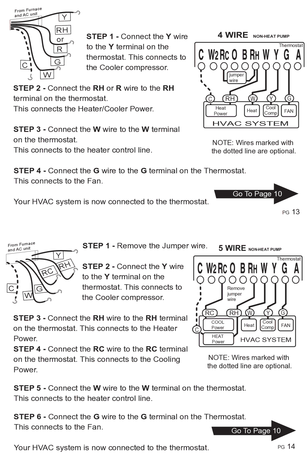
Finally, the Ritetemp 8050C is equipped with an easy installation process, featuring standard wiring that makes it compatible with most home systems. Whether upgrading from a manual thermostat or replacing a basic digital unit, the installation process is straightforward.
In conclusion, the Ritetemp 8050C is a dynamic and efficient thermostat that combines user-friendly programming with advanced technology. Its compatibility with various HVAC systems, programmable scheduling, and energy-saving features make it an outstanding choice for anyone seeking to enhance their home's climate control while maintaining comfort and efficiency.