VSW120 12” Subwoofer
Read First!
Installation
Speaker wire of 18 Gauge to 12 Gauge may be used with the VSW120C. You can purchase speaker wire with spade lug type female disconnects
Frequently Asked Questions
What if there is no sound?
1. Your stereo may have a blown fuse.
Replace fuse with the same amperage and style. 2. You may have improper wiring.
Dear Customer,
CONGRATULATIONS. The VSW120 Subwoofer, when used as described, will give you years of dependable service in your car, truck, RV or
Specifications
• 12” Embossed Polypropylene Cone | • 35 to 2000 Hz Frequency Response |
• 26.5 oz. Magnet Weight ±10% | • 2” ASV, Dual Voice Coil |
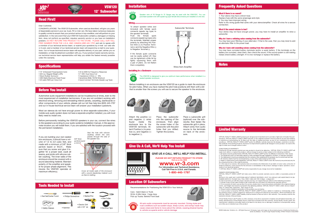
Wiring
To attach speaker wires (not included) with female quick connects (spade lug type) to the speaker terminals.
Push the female quick connects (spade lug type) onto the terminals. Maintain proper polarity by attaching the Posi- tive Wire (+) to Positive Termi- nal (+) and the Negative Wire
If the female quick connects can be easily pulled off, they can be tightened a little bit by lightly squeezing them with a pair of pliers. Do not flatten them completely.
Installing in a Enclosure
Subwoofer Terminals
Wires from Amplifier
Refer to the wiring guide that came with your stereo/amplifier. Check all wires for a secure connection.
What if the sound volume is low?
Your stereo may not have enough power, you may have to install an amplifier to drive a subwoofer.
Why do I have a whining noise coming from the subwoofer?
You may have poor filtering of your alternator. If that is the case, then you may need to add an alternator filter to the power lead.
Why do I have odd sounding noises coming from the subwoofer?
You may have corroded battery terminals and/or a weak battery. If the terminals on the battery are corroded, clean them; then check the sound. If the sound system is still making noises check battery strength. If it is low recharge or replace the battery.
Notes
• Black Rubber Surround | • Impedance 4 Ohms +/- 15% |
• 400 Watts Maximum Peak Power | • Sensitivity 89db 1W/1M Minimum |
• 40 watts RMS per Voice Coil | • Quick Connect Terminals (Spade Lug Type) |
Before You Install
Automotive audio equipment installations can be troublesome at times, even to the most experienced of installation technicians. If you are not confident working with electrical wiring, removing and reinstalling interior panels, carpeting, dashboards or other components of your vehicle, please call our toll free help line (800)
Most car stereos do not have enough power to drive separate subwoofers, if your mobile auto audio system does not have a separate amplifier installed, you will most likely need to install one.
Before permanently installing the VSW120 speakers in your car, connect the wires to the speakers according to your audio systems installation manual, in the approxi- mate location you will install them. If you are satisfied with the location proceed with the permanent installation.
The VSW120 is designed to give you optimum bass performance when installed in a sealed speaker enclosure.
Before installing in an enclosure use the VSW120 as a guide to mark the enclosure for pilot holes. When you have marked the pilot hole positions drill them with a bit that is smaller than the screws you will use to secure the speaker to the enclosure.
Attach the positive | (+) | Place | the | subwoofer | Place a subwoofer grill | ||
and negative | into the opening of the | (optional) over the sub- | |||||
found | inside | the | enclosure. | Then | align | woofer, then fasten the | |
enclosure | box to | the | the screw holes of the | subwoofer grill in place. | |||
VSW120 | terminals. At- | subwoofer with the pilot | Attach wires from audio | ||||
tach Positive (+) to posi- | holes | that | you | drilled. | source to the terminals | ||
tive (+), and negative | Tighten the screws. | on back of the enclo- | |||||
Limited Warranty
If you are building your own sealed box enclosure, it should have a vol- ume of 1.5 to 2.0 cubic feet, and made with a minimum of 5/8” thick particle board or M.D.F.. Make sure that you screw and glue it to- gether for a proper seal, caulk all seams, and joints with silicone rub- ber caulking. The inner walls of the enclosure should be covered with a sound absorbing material. Maintain polarity of the amplifier and speak- er for proper phase alignment. This insures the VSW120 operates at maximum efficiency.
Seal the hole with silicone caulking where the wire passes through the side of
5/8” thick the speaker box. particle board
or M.D.F.
Cover all inside walls of the enclosure with a sound deadening material such as Dacron batting.
to negative | sure. |
Give Us A Call, We’ll Help You Install
GIVE US A CALL, WE'LL HELP YOU INSTALL.
PLEASE DO NOT RETURN PRODUCT TO STORE.
Visit us on the WEB
For Information and Technical Assistance,
Call
Location Of Subwoofers
VIRTUAL REALITY VIDEO LABS® products are designed and manufactured to provide a high level of
CONDITIONS OF WARRANTY:
If during the 30 day warranty period your new product is found to be defective, VIRTUAL REALITY VIDEO LABS® will repair such defect, or replace the product, without charge for parts or labor subject to the following conditions:
1.All repairs must be performed by VIRTUAL REALITY VIDEO LABS® and/or its affiliates in Eatontown, New Jersey.
2.The equipment must not have been altered or been damaged through negligence, accident, or improper operation.
3.The replacement of parts are exempted from this warranty when replacement is necessary due to normal wear and tear.
4.All warranty claims must be accompanied by a copy of the sales receipt or bill of sale.
5.Repair or replacement parts supplied by VIRTUAL REALITY VIDEO LABS® under this warranty are protected only for the unexpired portion of the original warranty.
6.In the case of car stereos, this warranty does not extend to the elimination of car static or motor noise; correction of antenna problems; costs incurred for the removal or reinstallation of the product; damage to tapes, speakers, acces- sories or car electrical systems.
7.VIRTUAL REALITY VIDEO LABS® will not be responsible for any charge incurred for installation.
OWNER’S RESPONSIBILITIES:
VIRTUAL REALITY VIDEO LABS® will make every effort to provide warranty service within a reasonable period of time.
SHOULD YOU HAVE ANY QUESTIONS ABOUT SERVICE RECEIVED, OR IF YOU WOULD LIKE ASSISTANCE IN OB- TAINING SERVICE, PLEASE CALL TOLL FREE
In order to provide you with the proper warranty service, we request that you adhere to the following procedure:
1. Include a copy of your sales receipt or bill of sale with your unit when it is returned for warranty service. |
Tools Needed to Install
• Nail Set/Center Punch | • Phillips Screwdriver | • Marker/Pen | • Wire Cutter | |
|
|
|
| |
|
| • Electric Drill |
| |
• Safety Glasses | • Hammer | with 1/16" bit | • Electrical Tape | |
|
| |||
Recommendations for Positioning the VSW120 in Your Vehicle:
Cars: Hatch Back or Trunk
SUVs: & Mini Vans: Cargo Area
All auto audio components must be securely mounted. Driving styles and road conditions such as sudden stops, sharp curves, and bumpy roads may cause unsecured items to move about the vehicle, causing physical injuries to vehicle occupants and/or vehicle damage.
2. If it is necessary to return your product for service, please return it securely packed, preferably in the original shipping |
carton, and freight and insurance prepaid to the following address: VIRTUAL REALITY VIDEO LABS, Service Depart- |
ment, 41 James Way, Eatontown, New Jersey 07724. |
3. Please include a detailed explanation of the problem you are having. |
4. If your product is found by VIRTUAL REALITY VIDEO LABS® to have a defect in material or workmanship, within |
the warranty period, it will be repaired or replaced at no charge and returned to you prepaid. Where permitted by Iaw |
VIRTUAL REALITY VIDEO LABS® liability shall be limited to that set forth in this warranty. This warranty shall be the |
exclusive remedy of the purchaser. |
Virtual Reality Sound Labs® makes no other warranty of any kind, expressed or implied; and all implied warranties, are hereby disclaimed by Virtual Reality Sound Labs® and excluded from this warranty, Virtual Reality Sound Labs®, the manufacturer, distributor and seller shall not be liable for any injury, loss or damage, incidental or consequential, arising out of the use or intended use of the product
©2008 Intellectual Solutions, Inc., All Rights Reserved. All designs, logos and images are the exclusive property of Intellectual Solutions Inc. and/or its affilantes. US and Foreign Patents Pending. 071608 Printed in China 00000