Manuals
/
Rockford Fosgate
/
Home Audio
/
Stereo Amplifier
Rockford Fosgate
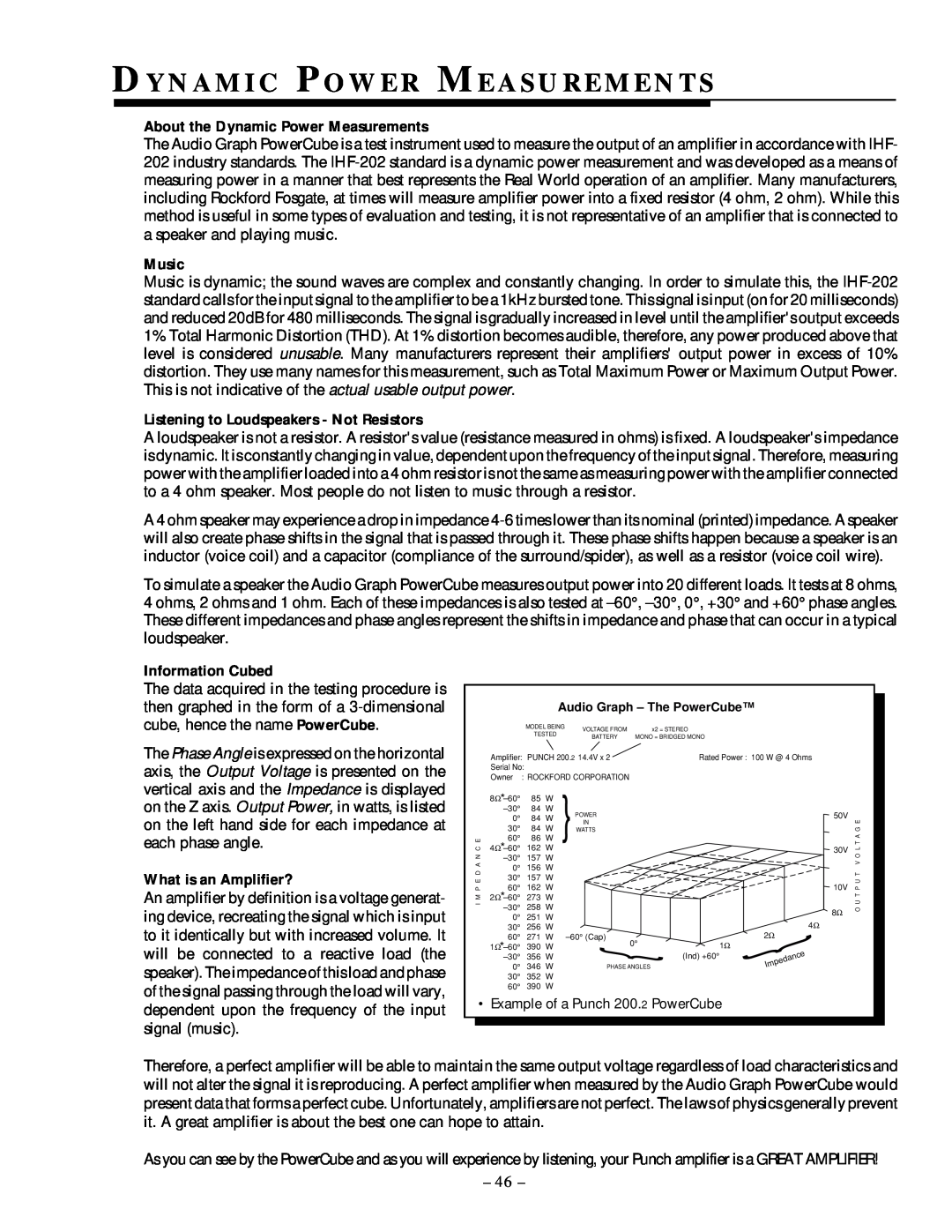
250.1 Dy N A M I C Po W E R Me A S U R E M E N T S, Music, Information Cubed
Models:
250.1
1
49
62
62
Download
62 pages
41.7 Kb
46
47
48
49
50
51
52
53
Performance Characteristics
Install
Xca R D Resistor Chart
U S I N G T H E 250.1 SIGNAL
Connecting the BLT
Warranty
Configurea12dBper
Symptom
Rockford Fosgate Accessories
Battery And Charging
Page 49
Image 49
Page 48
Page 50
Page 49
Image 49
Page 48
Page 50
Contents
power
power
power
250.1
PRACTICE SAFE SOUND
G E T T I N G S T A R T E D
TA B L E O F CO N T E N T S
INTRODUCTION TO 250 SERIES
Punch Power
Punch Power
DIABLO Dynamically Invariant A-BLinear Operation
TECHNICAL DESIGN FEATURES
TOPAZ Tracking Operation Pre-AmplifierZone
trans nova circuitry
DSM Discrete Surface Mount Technology
Stereo Pass-Thru
XCard Internal Crossover
NOMAD NOn-MultiplyingAdvanced Decision
Balanced Line Inputs
ITS Increased Thermal Stability
250.2 DE S I G N FE AT U R E S
PLIFIER
250.1 DE S I G N FE AT U R E S
1AMPLIFIER
Tools Needed
INSTALLATION CONSIDERATIONS
Trunk Mounting
BATTERY AND CHARGING
Passenger Compartment Mounting
Engine Compartment Mounting
W I R I N G T H E S Y S T E M
USING PASSIVE CROSSOVERS
6 dB/Octave High-Pass
TABLE OF CROSSOVER COMPONENT VALUES
6 dB/Octave Low-Pass
Freq
CU S T O M I Z I N G T H E XCA R D
US I N G T H E XCARD
High-Pass
Low-Pass
Butterworth Alignment Q =
XCA R D RESISTOR CHART
1% resistors used with 0.047∝ F capacitors
Butterworth Alignment Q =
250.2 Power Connections Option #1
250.2 INSTALLATION
250.2 Power Connections Option #2
Stereo/Mono Operation
Stereo Operation
Left Phase Switch set to
Right Phase Switch set to
EZ-BridgedOperation
Bridged Operation
Left Phase Switch set to
Right Phase Switch set to
Page
XCard not required
Pass-Thru uses output from XCard
250.2 uses output from XCard
Page
Configurea24dBperoctave and“AudiophileBypass”the
Configurea12dBper
filterfor
Pass-Thru
Connecting the BLT
USING THE 250.2 BALANCED LINE INPUTS
8.0 VAC
Level Setting the BLT
Performance Characteristics
Disconnect Speakers from the
250.1 Power Connections Option #1
250.1 INSTALLATION
250.1 Power Connections Option #2
Phase Switch set to
Mono Operation
minimum
orFullRange
AmplifiersPower
Impedanceforeachstereochannelshouldbe2Ω minimum
Stereo/Mono Operation
Impedanceforbridgedchannelshouldbe4Ω minimum
minimum
Bridged Mono Operation
Impedanceforbridgedchannelshouldbe4Ω
Pass,-High -LoworPass RangeFull
S W I T C H I N G N E T W O R K
U S I N G T H E 250.1 SIGNAL
“Audiophile Bypass” the
XCard
Configure a 12dB per octave filter for the
LOUD
TUNE
Configure a 24dB per octave filter for the
250 Watt System rated @ 4 ohms
SY S T E M DI A G R A M S
Total Power Delivery RMS
Total Power Delivery RMS
500 Watt System rated @ 4 ohms
Total Power Delivery RMS
750 Watt System rated @ 4 ohms
Tweeters
450 Watts
Total Power Delivery RMS
1000 Watt System rated @ 4 ohms
Tweeters
Watts
NOISE
ROCKFORD FOSGATE ACCESSORIES
Balanced Line Transmitter FG-BLT
Punch Status Display connected to one
Punch Status Display FG-PSD
Channel A monitors left channel
Channel B monitors right channel
Energy Storage Capacitors
punch
XCard Crossovers
1.0cap
TR O U B L E S H O O T I N G
Symptom
Diagnosis
Remedy
Diagnosis
Symptom
Remedy
Speaker Output Low
Diagnosis
Symptom
Remedy
Low or distorted output from
AUTOSOUND 2000s
QUICK CHECK FOR TROUBLESHOOTING CAR AUDIO SYSTEMS
Preface
Noise Overview
Summation
Time for Processors
About the Dynamic Power Measurements
DY N A M I C PO W E R ME A S U R E M E N T S
What is an Amplifier?
Music
Specifications subject to change without notice
250.2 SP E C I F I C AT I O N S
180Watts 310Watts 620Watts 125Watts 225Watts
450 Watts
Specifications subject to change without notice
250.1 SP E C I F I C AT I O N S
420Watts 710Watts 1420 Watts 250Watts 500 Watts
1000 Watts
Length of Warranty
LIMITED WA R R A N T Y IN F O R M AT I O N
What is Covered
What is Not Covered
N F O R M A T I O N
UBICACIÓN DE LOS AMPLIFICADORES
INTRODUCCIÓN
Maletero
Habitáculo
Operación mono/estéreo
INTRODUCTION
Installation
MONTAGE
Montage dans le coffre
Page
EINBAUORT
EINLEITUNG
DEUTSCH
Im Fahrzeugkofferraum
Stereo/Mono Betrieb
Linken Phasen Schalter auf 0 stellen
INTRODUZIONE
Installazione
DOVE POSIZIONARLO
ITALIANO
Fase sinistra dellinterruttore posizionata su
Stereo/Mono Operation
MADE IN THE USA
Top
Page
Image
Contents