Power
4.Cover the crimped area with the protective boot that is supplied with the fuse holder.
5.Repeat the above steps to connect the remainder of the red power wire to the other side of the fuse holder and route to the amplifier mounting location.
Wiring the Power Connectors
1. Strip back approximately 3/8" (.95cm) of wire.
![]() 3/8"
3/8" ![]()
(.95cm)
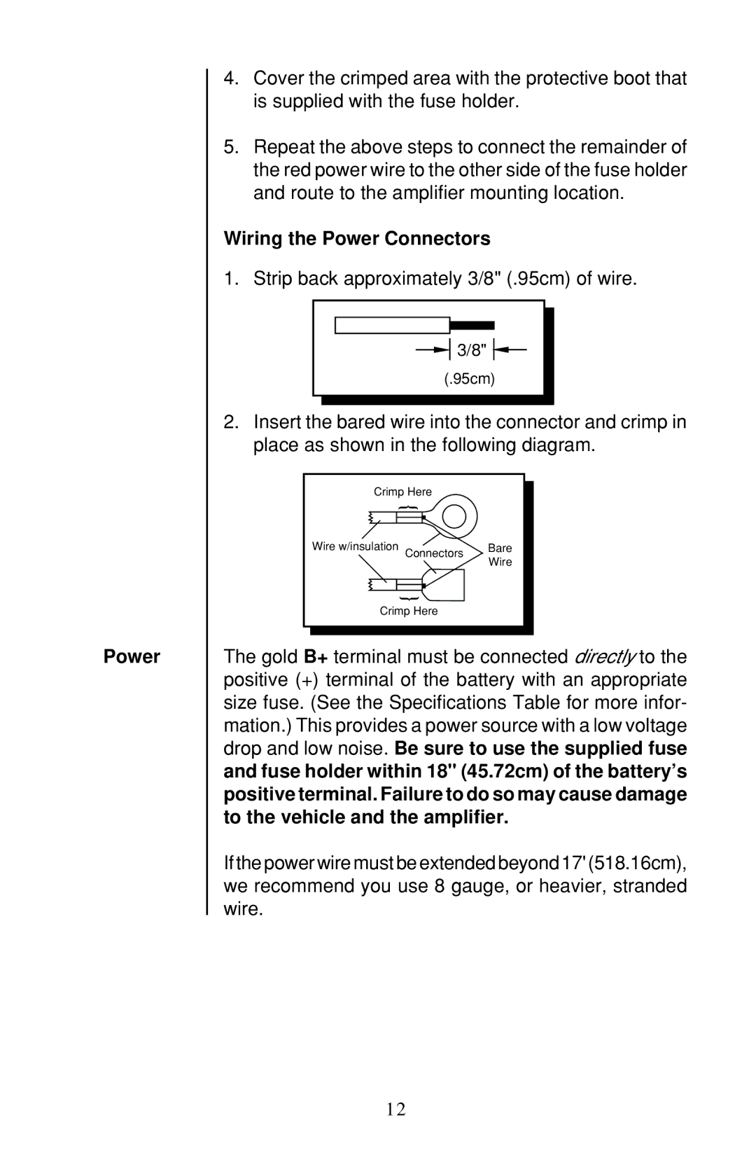
2.Insert the bared wire into the connector and crimp in place as shown in the following diagram.
Crimp Here |
| |
| { |
|
Wire w/insulation | Connectors | Bare |
| Wire | |
|
| |
| { |
|
Crimp Here |
| |
The gold B+ terminal must be connected directly to the positive (+) terminal of the battery with an appropriate size fuse. (See the Specifications Table for more infor- mation.) This provides a power source with a low voltage drop and low noise. Be sure to use the supplied fuse and fuse holder within 18" (45.72cm) of the battery’s positive terminal. Failure to do so may cause damage to the vehicle and the amplifier.
If the power wire must be extended beyond 17' (518.16cm), we recommend you use 8 gauge, or heavier, stranded wire.
12