•Place the speakers where they have a direct path to the listening area.
• When using the Punch Splits, there are two options for speaker place-
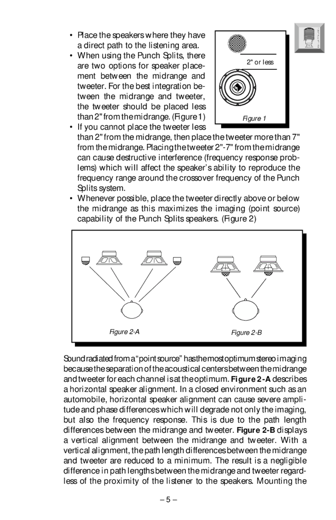
ment between the midrange and tweeter. For the best integration be- tween the midrange and tweeter,
the tweeter should be placed less than 2" from the midrange. (Figure 1)
• If you cannot place the tweeter less ![]() than 2" from the midrange, then place the tweeter more than 7" from the midrange. Placing the tweeter
than 2" from the midrange, then place the tweeter more than 7" from the midrange. Placing the tweeter
•Whenever possible, place the tweeter directly above or below the midrange as this maximizes the imaging (point source) capability of the Punch Splits speakers. (Figure 2)
I
N S T A L L A T I O N
|
|
|
|
|
|
|
|
|
|
|
|
|
|
|
|
|
|
|
|
|
|
|
|
|
|
|
|
|
|
|
|
|
|
|
|
|
|
|
|
|
|
|
|
|
|
|
|
|
|
|
|
|
|
|
|
|
|
|
|
|
|
|
|
|
|
|
|
|
|
|
|
|
|
|
|
|
|
|
|
|
|
|
|
|
|
|
|
|
|
|
|
|
|
|
|
|
|
|
|
|
|
|
|
|
|
|
|
|
|
|
|
|
|
|
|
|
|
|
|
|
|
|
|
|
|
|
|
|
|
|
|
|
|
|
|
|
|
|
|
|
|
|
|
|
|
|
|
|
|
|
|
|
|
|
|
|
|
|
|
|
|
|
|
|
|
|
|
|
|
|
|
|
|
|
|
|
|
|
|
|
|
|
|
|
|
|
|
|
|
|
|
|
|
|
|
|
|
|
|
|
|
|
|
|
|
|
|
|
|
|
|
|
|
|
|
|
|
|
|
|
|
|
|
|
|
|
|
|
|
|
|
|
|
|
|
|
|
|
|
|
|
|
|
|
|
|
|
|
|
|
|
|
|
|
|
|
|
|
|
|
|
|
|
|
|
|
|
|
|
|
|
|
|
|
|
|
|
|
|
|
|
|
|
|
|
|
|
|
|
|
| Figure |
|
|
| Figure |
| ||||||||||||||||||||||
|
|
|
|
|
|
|
|
|
|
|
|
|
|
|
|
|
|
|
|
|
|
|
|
|
|
|
|
|
|
|
|
|
|
|
|
|
|
|
|
|
|
|
|
|
|
|
|
|
|
|
|
|
|
|
|
|
|
|
|
|
|
|
|
Soundradiatedfroma“pointsource”hasthemostoptimumstereo imaging because the separation of the acoustical centers between the midrange and tweeter for each channel is at the optimum. Figure
– 5 –