DESIGN FEATURES
1 | 3 | 4 | 5 | 6 | 7 | 6 | 5 | 4 | 3 | 2 |
| 8 9 8 10 | 11 |
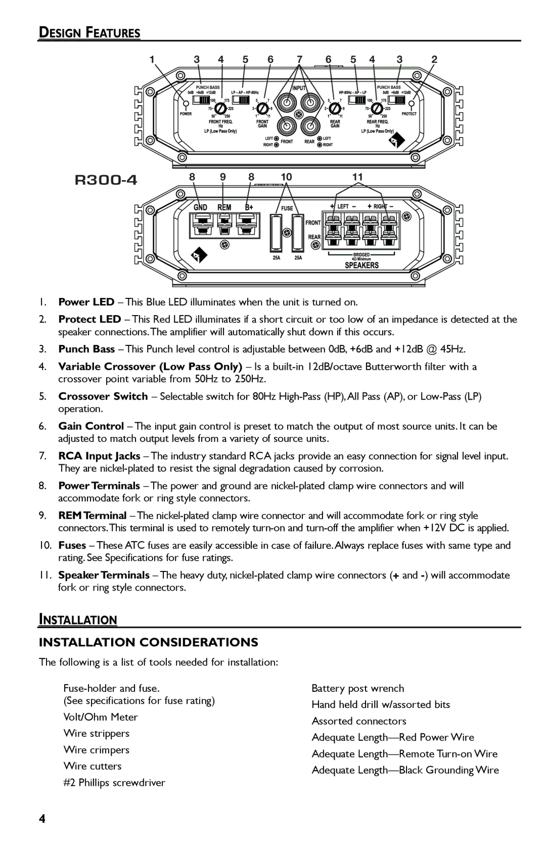
1.Power LED – This Blue LED illuminates when the unit is turned on.
2.Protect LED – This Red LED illuminates if a short circuit or too low of an impedance is detected at the speaker connections.The amplifier will automatically shut down if this occurs.
3.Punch Bass – This Punch level control is adjustable between 0dB, +6dB and +12dB @ 45Hz.
4.Variable Crossover (Low Pass Only) – Is a
5.Crossover Switch – Selectable switch for 80Hz
6.Gain Control – The input gain control is preset to match the output of most source units. It can be adjusted to match output levels from a variety of source units.
7.RCA Input Jacks – The industry standard RCA jacks provide an easy connection for signal level input. They are
8.Power Terminals – The power and ground are
9.REMTerminal – The
10.Fuses – These ATC fuses are easily accessible in case of failure.Always replace fuses with same type and rating. See Specifications for fuse ratings.
11.Speaker Terminals – The heavy duty,
INSTALLATION
INSTALLATION CONSIDERATIONS
The following is a list of tools needed for installation:
(See specifications for fuse rating) Volt/Ohm Meter
Wire strippers Wire crimpers Wire cutters
#2 Phillips screwdriver
Battery post wrench
Hand held drill w/assorted bits Assorted connectors
Adequate
4