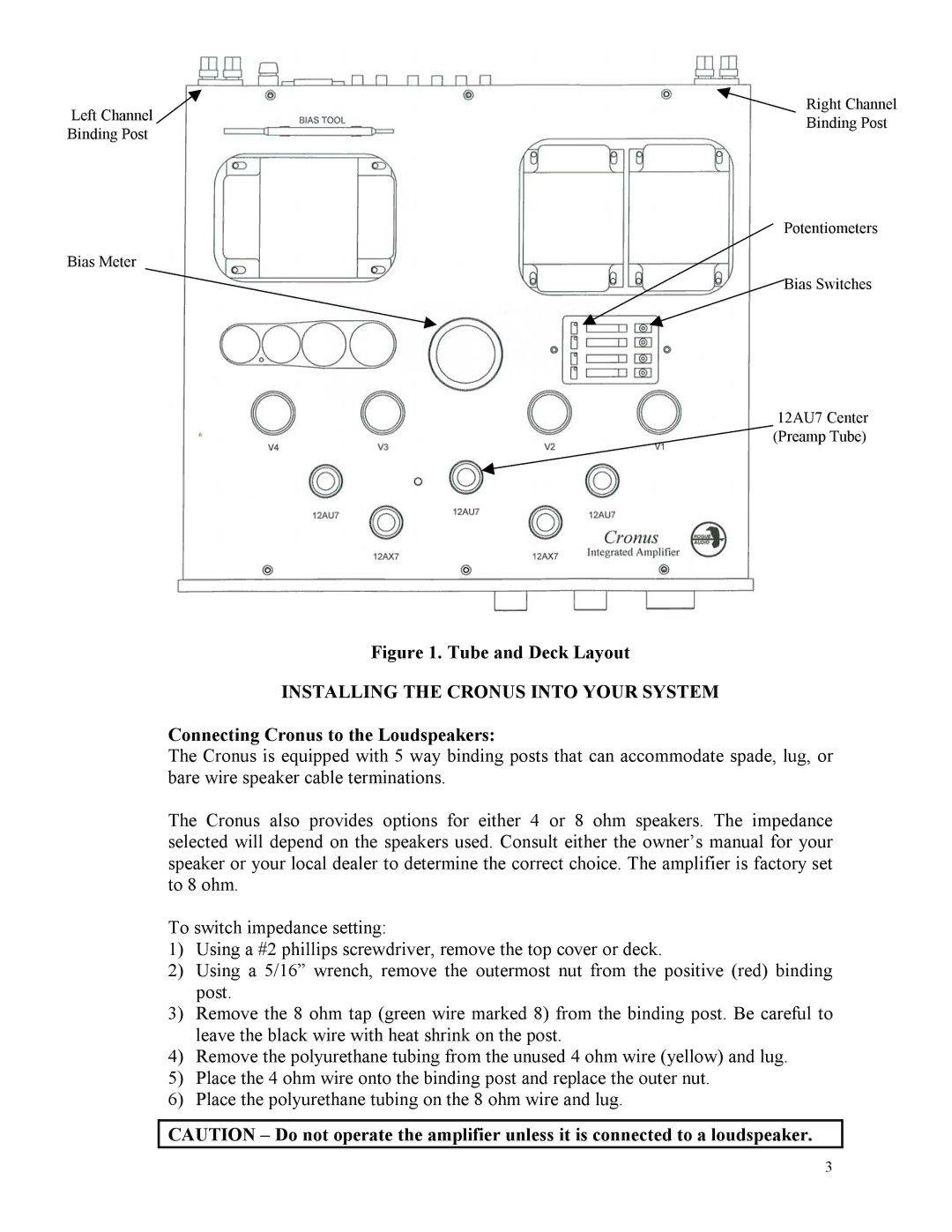
Left Channel ![]() Binding Post
Binding Post
Bias Meter
Right Channel
Binding Post
Potentiometers
![]() Bias Switches
Bias Switches
12AU7 Center
![]() (Preamp Tube)
(Preamp Tube)
Figure 1. Tube and Deck Layout
INSTALLING THE CRONUS INTO YOUR SYSTEM
Connecting Cronus to the Loudspeakers:
The Cronus is equipped with 5 way binding posts that can accommodate spade, lug, or bare wire speaker cable terminations.
The Cronus also provides options for either 4 or 8 ohm speakers. The impedance selected will depend on the speakers used. Consult either the owner’s manual for your speaker or your local dealer to determine the correct choice. The amplifier is factory set to 8 ohm.
To switch impedance setting:
1)Using a #2 phillips screwdriver, remove the top cover or deck.
2)Using a 5/16” wrench, remove the outermost nut from the positive (red) binding post.
3)Remove the 8 ohm tap (green wire marked 8) from the binding post. Be careful to leave the black wire with heat shrink on the post.
4)Remove the polyurethane tubing from the unused 4 ohm wire (yellow) and lug.
5)Place the 4 ohm wire onto the binding post and replace the outer nut.
6)Place the polyurethane tubing on the 8 ohm wire and lug.
CAUTION – Do not operate the amplifier unless it is connected to a loudspeaker.
3