LIII specifications
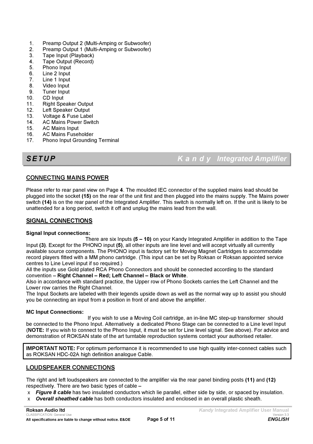
Roksan Audio has long been synonymous with high-quality audio equipment, and the Roksan LIII is a testament to the brand’s commitment to delivering exceptional sound performance. This integrated amplifier stands at the forefront of modern audio technology, combining elegance, power, and versatile connectivity.At the heart of the Roksan LIII is its robust power output, delivering 140 watts per channel into 8 ohms. This substantial power enables the amplifier to drive a wide variety of speakers, from efficient bookshelf models to more demanding floorstanders, ensuring a dynamic and engaging listening experience. The amplifier's ability to maintain clarity and precision at all volume levels is a hallmark of Roksan's engineering prowess.
One of the most notable features of the Roksan LIII is its Class A/B amplification topology. This design provides the warmth and richness associated with Class A amplifiers while also benefiting from the efficiency of Class B designs. As a result, listeners can expect a balanced tonal quality with a full-bodied sound that enhances vocals and instrumentals alike.
The Roksan LIII incorporates advanced circuitry aimed at reducing distortion and noise, ensuring that the audio signal remains pure and true to the original recording. High-quality components, including premium capacitors and resistors, further contribute to the amplifier's stellar performance. The attention to detail in the design process ensures that every note is rendered with accuracy, allowing audiophiles to enjoy their music as it was meant to be heard.
Connectivity options on the LIII are expansive. It features multiple line inputs, allowing users to connect various sources, such as CD players, streamers, and turntables. For vinyl enthusiasts, the integrated phono stage is a welcome addition, delivering exceptional performance for both moving magnet and moving coil cartridges. Furthermore, the amplifier's pre-out and power-in connections provide flexibility for those looking to integrate additional audio components or to create a bi-amped setup.
The design of the Roksan LIII is both stylish and functional, with a sleek chassis that complements any home audio setup. The intuitive front panel interface includes a large volume knob and input selector buttons, making it easy for users to navigate their audio sources seamlessly.
In conclusion, the Roksan Audio LIII integrated amplifier embodies excellence in sound reproduction, offering a blend of power, clarity, and user-friendly features. With its modern technologies, robust build quality, and sophisticated design, the LIII stands as a remarkable choice for anyone looking to elevate their audio experience. Whether you're an avid music lover or a dedicated audiophile, the Roksan LIII is sure to impress.

