Roper Range installation instructions T ifI, Electronic Ignition System

Models: Range

1 7
Download 7 pages 7.32 Kb
Page 4
Image 4
T ifI

8n

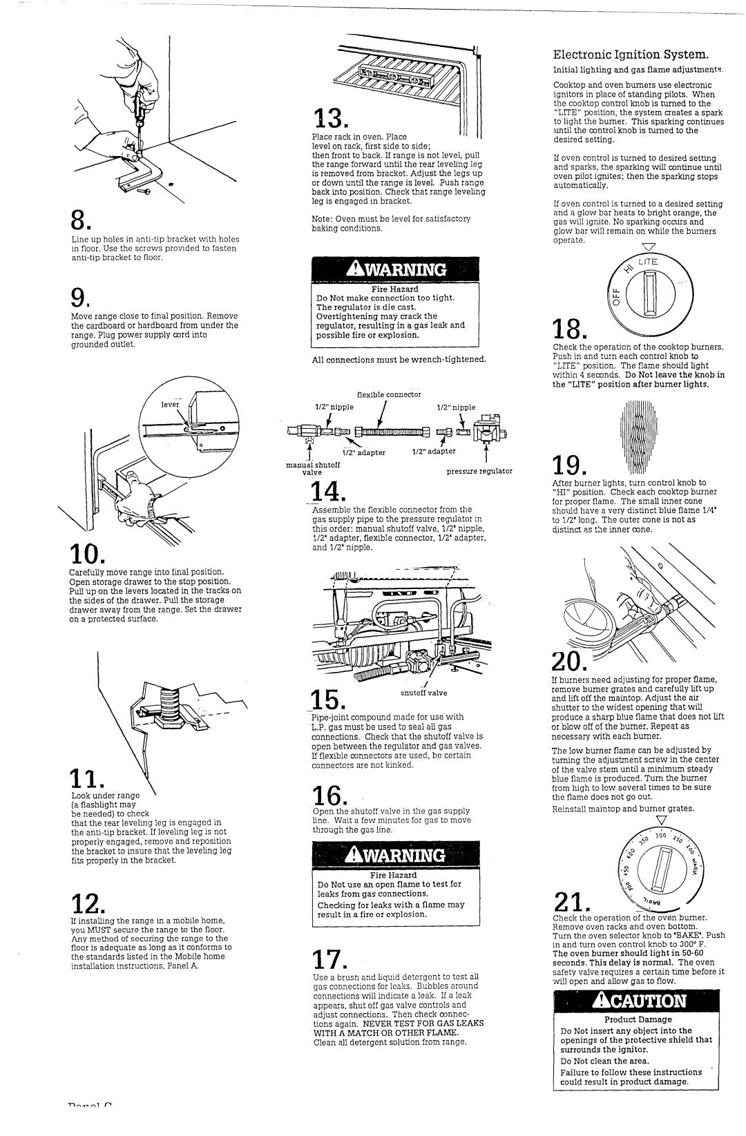
Line up holes in anti-tip bracket with holes in floor. Use the screws provided to fasten anti-tip bracket to floor.

a

Jt

Move range close to final position. Remove the cardboard or hardboard from under the range. Plug power supply cord into grounded outlet.

Carefully move range into final position. Open storage drawer to the stop position. Pull up on the levers located in the tracks on the sides of the drawer. Pull the storage drawer away from the range. Set the drawer on a protected surface.

13.

Place rack in oven. Place

level on rack, first side to side;

then front to back. If range is not level, pull the range forward until the rear leveling leg is removed from bracket. Adjust the legs up or down until the range is level. Push range back into position. Check that range leveling leg is engaged in bracket.

Note: Oven must be level for satisfactory baking conditions.

Fire Hazard

Do Not make connection too tight. The regulator is die cast. Overtightening may crack the regulator, resulting in a gas leak and possible fire or explosion.

All connections must be wrench-tightened.


flexible

connector

l/2” nipple

/

112”nipple


T ifI


112” adapter

mandi shutoff


I


pressure regulator

valve


--14n

Assemble the flexible connector from the gas supply pipe to the pressure regulator in this order: manual shutoff valve, l/2’ nipple, l/2’ adapter, flexible connector, l/2’ adapter, and l/2” nipple.

_-

Electronic Ignition System.

Initial lighting and gas flame adjustments.

Cooktop and oven burners use electronic ignitors in place of standing pilots. When the cooktop control knob is turned to the “LlTE” position, the system creates a spark to light the burner. This sparking continues until the control knob is turned to the desired setting.

If oven control is turned to desired setting and sparks, the sparking will continue until oven pilot ignites: then the sparking stops automatically.

If oven control is turned to a desired setting and a glow bar heats to bright orange, the gas will ignite. No sparking occurs and glow bar will remain on while the burners

operate.

Y-7

18n

Check the operation of the cooktop burners. Push in and turn each control knob to “LITE” position. The flame should light within 4 seconds. Do Not leave the knob in the “LITE” position after burner lights.

19m

After burner lights, turn control knob to “HI” position. Check each cooktop burner for proper flame. The small inner cone should have a very distinct blue flame l/4’ to l/2’ long. The outer cone is not as distinct as the inner cone.

Look under range (a flashlight may be needed) to check

that the rear leveling leg is engaged in the anti-tip bracket. If leveling leg is not properly engaged, remove and reposition the bracket to insure that the leveling leg fits properly in the bracket.

12m

If installing the range in a mobile home, you MUST secure the range to the floor. Any method of securing the range to the floor is adequate as long as it conforms to the standards listed in the Mobile home installation instructions, Panel A.

-1

shutoff valve

Pipe-joint compound made for use with L.P. gas must be used to seal all gas connections. Check that the shutoff valve is open between the regulator and gas valves. If flexible connectors are used, be certain connectors are not kinked.

16.

Open the shutoff valve in the gas supply line. Wait a few minutes for gas to move through the gas line.

Do Not use an open flame to test for leaks from gas connections.

Checking for leaks with a flame may result in a fire or explosion.

17.

Use a brush and liquid detergent to test all gas connections for leaks. Bubbles around connections will indicate a leak. If a leak appears, shut off gas valve controls and adjust connections. Then check connec- tions again. NEVER TEST FOR GAS LEAKS WITH A MATCH OR OTHER FLAXIIE. Clean all detergent solution from range.

If burners need adjusting for proper flame, remove burner grates and carefully lift up and lift off the maintop. Adjust the air shutter to the widest opening that will produce a sharp blue flame that does not lift or blow off of the burner. Repeat as necessary with each burner.

The low burner flame can be adjusted by turning the adjustment screw in the center of the valve stem until a minimum steady blue flame is produced. Turn the burner from high to low several times to be sure the flame does not go out.

Reinstall maintop and burner grates.

21.

Check the operation of the oven burner. Remove oven racks and oven bottom.

Turn the oven selector knob to ‘BAKE’. Push in and turn oven control knob to 300” F.

The oven burner should light in SO-60 seconds. This delay is normal. The oven safety valve requires a certain time before it will open and allow gas to flow.

Product Damage

Do Not insert any object into the openings of the protective shield that surrounds the ignitor.

Do Not clean the area.

Failure to follow these instructions . could result in product damage.

Page 4
Image 4
Roper Range installation instructions T ifI, Electronic Ignition System