D.
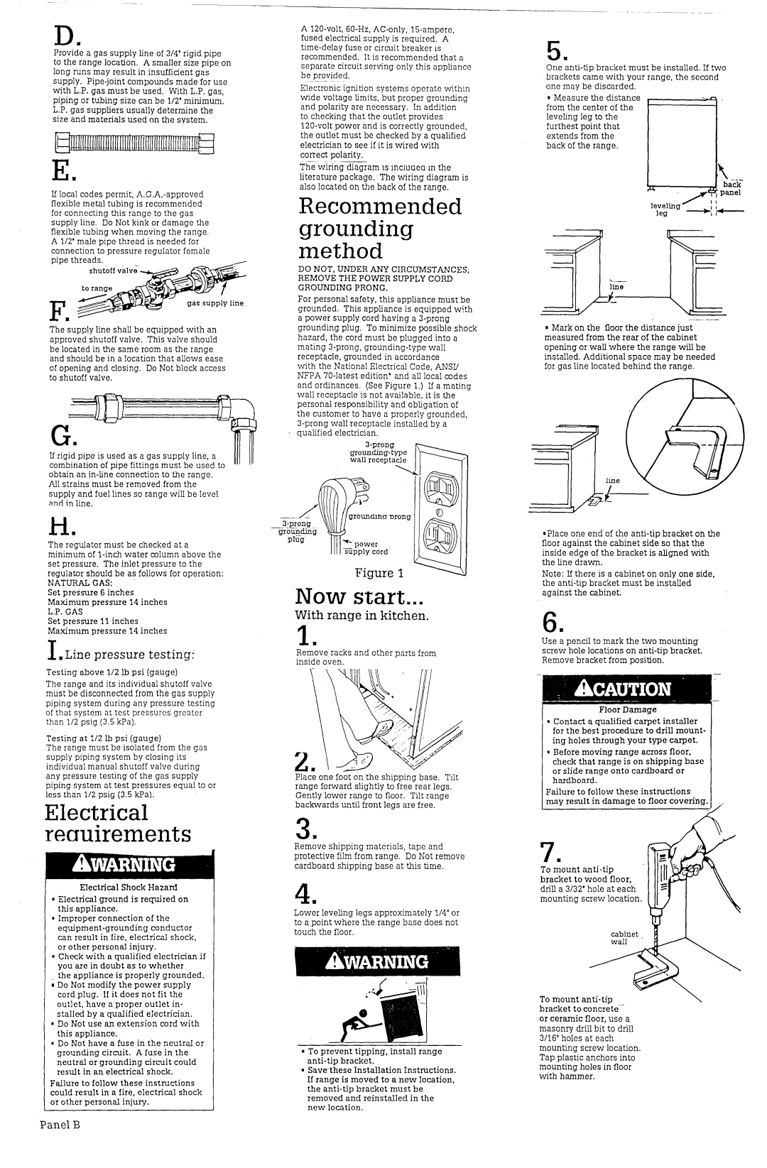
Provide a gas supply line of 314’ rigid pipe to the range location. A smaller size pipe on long runs may result in insufficient gas supply. Pipe-joint compounds made for use with L.P. gas must be used. With L.P. gas, piping or tubing size can be l/2’ minimum. L.P. gas suppliers usually determine the size and materials used on the system.
Em
If local codes permit, A.G.A.-approved flexible metal tubing is recommended for connecting this range to the gas supply line. Do Not kink or damage the flexible tubing when moving the range. A l/2’ male pipe thread is needed for connection to pressure regulator female pipe threads.
Fm
The supply line shall be equipped with an approved shutoff valve. .This valve should be located in the same room as the range and should be in a location that allows ease of opening and closing. Do Not block access to shutoff valve.
If rigid pipe is used as a gas supply line, a combination of pipe fittings must be used to obtain an in-line connection to the range.
All strains must be removed from the supply and fuel lines so range will be level and in line.
H .
The regulator must be checked at a minimum of l-inch water mlumn above the set pressure. The inlet pressure to the regulator should be as follows for operation:
NATURAL GAS:
Set pressure 6 inches Maximum pressure 14 inches L.P. GAS
Set pressure 11 inches Maximum pressure 14 inches
I , Line pressure testing:
Testing above l/2 lb psi (gauge)
The range and its individual shutoff valve must be disconnected from the gas supply piping system during any pressure testing of that system at test pressures’ greater than l/2 psig (3.5 kPa).
Testing at l/2 Ib psi (gauge)
The range must be isolated from the gas supply piping system by closing its individual manual shutoff valve during any pressure testing of the gas supply piping system at test pressures equal to or less than l/2 psig (3.5 kPa).
Electrical recruirements
Electrical Shock Hazard
. Electrical ground is required on this appliance.
1 Improper connection of the equipment-grounding conductor can result in fire, electrical shock, or other personal injury.
. Check with a qualified electrician if you are in doubt as to whether
the appliance is properly grounded.
;Do Not modify the power supply cord plug. If it does not fit the
outlet, have a proper outlet in- stalled by a qualified electrician.
a Do Not use an extension cord with this appliance.
. Do Not have a fuse in the neutral or grounding circuit. A fuse in the neutral or grounding circuit could result in an electrical shock.
Failure to follow these instructions could result in a fire, electrical shock or other personal injury.
A 120-volt, 60-Hz, AC-only, 15-ampere, fused electrical supply is required. A time-delay fuse or circuit breaker is recommended. It is recommended that a separate circuit serving only this appliance be provided.
Electronic ignition systems operate within wide voltage limits, but proper grounding and polarity are necessary. In addition to checking that the outlet provides
120-volt power and is correctly grounded, the outlet must be checked by a qualified electrician to see if it is wired with correct polarity.
The wi&gzarn is incluaea in the literature package. The wiring diagram is also located on the back of the range.
Recommended grounding method
DO NOT, UNDER ANY CIRCUMSTANCES, REMOVE THE POWER SUPPLY CORD GROUNDING PRONG.
For personal safety, this appliance must be grounded. This appliance is equipped with a power supply cord having a 3-prong grounding plug. To minimize possible shock hazard, the cord must be plugged into a mating 3-prong, grounding-type wall receptacle, grounded in accordance
with the National Electrical Code, ANSI/ NFPA 70-latest edition* and all local codes and ordinances. (See Figure 1.) If a mating wall receptacle is not available, it is the personal responsibility and obligation of the customer to have a properly grounded, 3-prong wall receptacle installed by a qualified electrician.
&prong grounding-type wall rccmtacle
@fl
--.LI’ -_-3-proqg@
Qr;gJw
Figure 1 1;;;1
Now start...
With range in kitchen.
1.
Remove racks and other parts from inside oven.
r
L
Place one fobt on the shipping base. Tilt range forward slightly to free rear legs. Gently lower range to floor. Tilt range backwards until front legs are free.
3m
Remove shipping materials, tape and protective film from range. Do Not remove cardboard shipping base at this time.
4.
Lower leveling legs approximately l/4” or to a point where the range base does not touch the floor.
. To prevent tipping, install range anti-tip bracket.
. Save-these Installation Instructions. If range is moved to a new location, the anti-tip bracket must be removed and reinstalled in the
new loation.
5
One:nti-tip bracket must be installed. If two brackets came with your range, the second one may be discarded.
n Measure the distance from the center of the leveling leg to the furthest point that extends from the back of the range.
a Mark on the floor the distance just measured from the rear of the cabinet opening or wall where the range will be installed. Additional space may be needed for gas line located behind the range.
--
.Place one end of the anti-tip bracket on the floor against the cabinet side so that the inside edge of the bracket is aligned with the line draw-n.
Note: If there is a cabinet on only one side, the anti-tip bracket must be installed against the cabinet.
6m
Use a pencil to mark the two mounting screw hole locations on anti-tip bracket. Remove bracket from position.
Floor Damage
mContact (I qualified carpet installer for the best procedure to drill mount- ing holes through your type carpet.
mBefore moving range across floor, check that range is on shipping base or slide range onto cardboard or hardboard.
Failure to follow these instructions
may result in damage to floor covering.
To mount anti-tip bracket to wood floor, drill a 3132’ hole at each mounting screw location.
To mount anti-tip bracket to concrete-
.or ceramic floor, use a masonry drill bit to drill 3/16” holes at each mounting screw location. Tap plastic anchors into mounting holes in floor with hammer.