SECTION 9—MOTORS
B.Run the motors forward for one hour.
C.Turn motors off and allow 30 minutes for motors to cool off.
D.Run the motors in reverse for one hour.
E.When process is complete, remove wheelchair from blocks and test drive the wheelchair.
NOTE: If wheelchair still does not perform properly, call Invacare Technical Service at
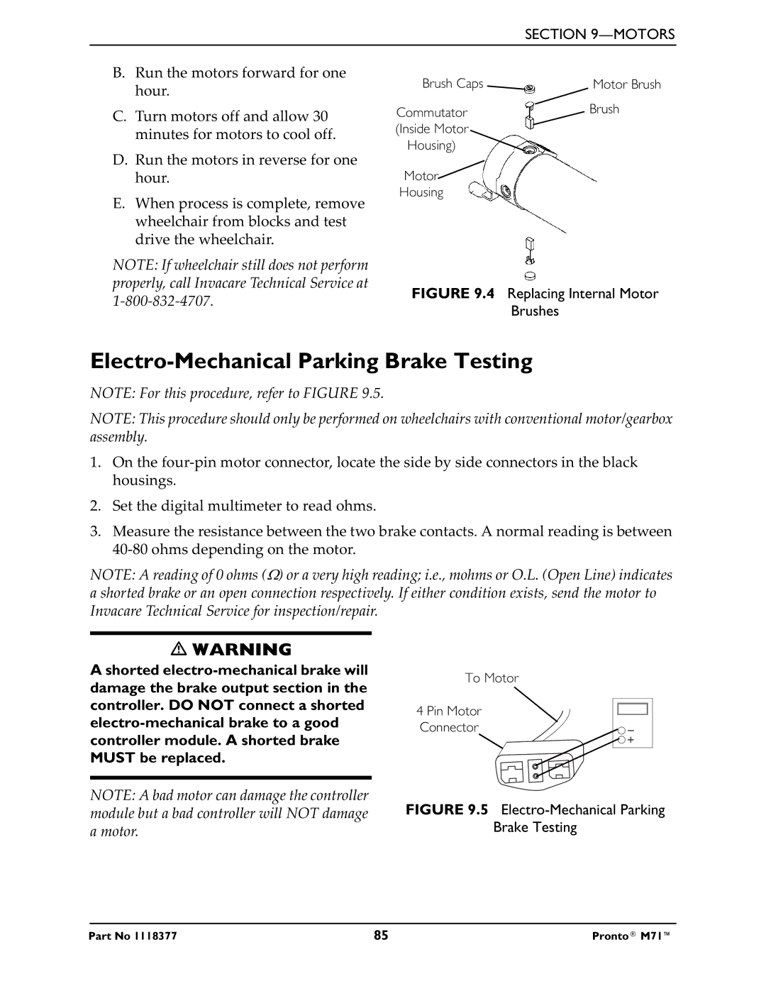
Brush Caps | Motor Brush |
Commutator | Brush |
| |
(Inside Motor |
|
Housing) |
|
Motor |
|
Housing |
|
FIGURE 9.4 Replacing Internal Motor
Brushes
Electro-Mechanical Parking Brake Testing
NOTE: For this procedure, refer to FIGURE 9.5.
NOTE: This procedure should only be performed on wheelchairs with conventional motor/gearbox assembly.
1.On the
2.Set the digital multimeter to read ohms.
3.Measure the resistance between the two brake contacts. A normal reading is between
NOTE: A reading of 0 ohms (Ω) or a very high reading; i.e., mohms or O.L. (Open Line) indicates a shorted brake or an open connection respectively. If either condition exists, send the motor to Invacare Technical Service for inspection/repair.
WARNING
A shorted
NOTE: A bad motor can damage the controller module but a bad controller will NOT damage a motor.
To Motor
4 Pin Motor
Connector
FIGURE 9.5 Electro-Mechanical Parking
Brake Testing
Part No 1118377 | 85 | Pronto® M71™ |