SECTION
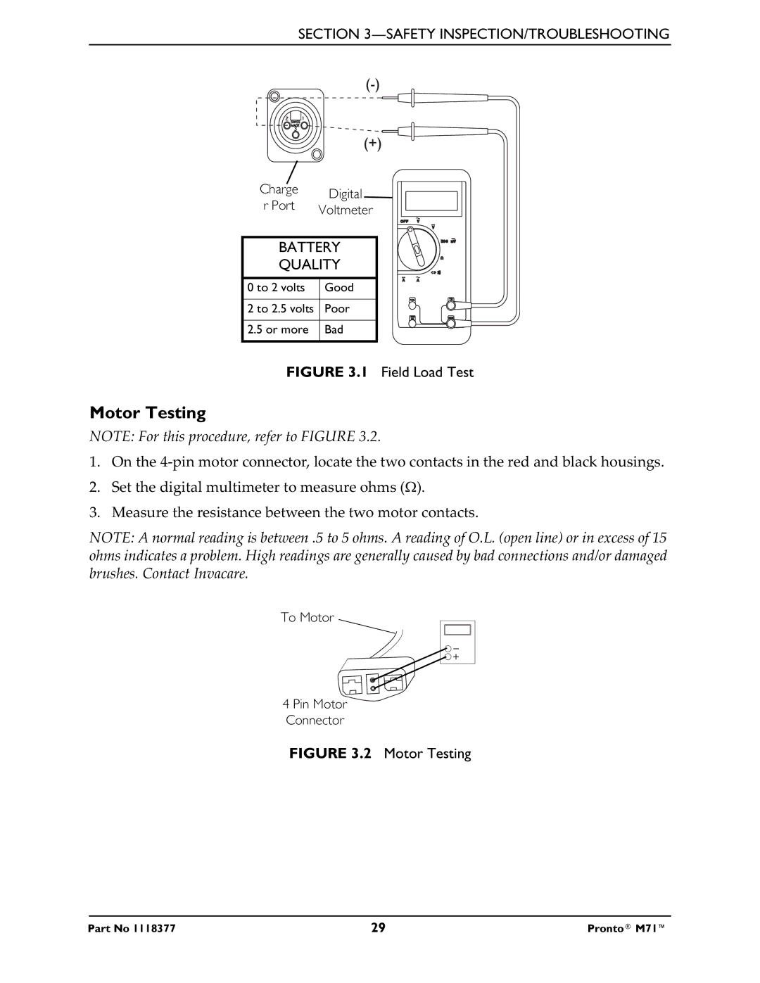
Charge | Digital | |
r Port | ||
Voltmeter | ||
|
BATTERY
QUALITY
0 to 2 volts | Good |
|
|
2 to 2.5 volts | Poor |
|
|
2.5 or more | Bad |
|
|
FIGURE 3.1 Field Load Test
Motor Testing
NOTE: For this procedure, refer to FIGURE 3.2.
1.On the
2.Set the digital multimeter to measure ohms (Ω).
3.Measure the resistance between the two motor contacts.
NOTE: A normal reading is between .5 to 5 ohms. A reading of O.L. (open line) or in excess of 15 ohms indicates a problem. High readings are generally caused by bad connections and/or damaged brushes. Contact Invacare.
To Motor
4 Pin Motor
Connector
FIGURE 3.2 Motor Testing
Part No 1118377 | 29 | Pronto® M71™ |