|
| SECTION | ||||
Left Side Frame | 2 | Left Side Frame |
|
| ||
Assembly | Label #2 |
|
| |||
|
|
| ||||
NOTE: View is from inside of |
|
|
|
|
| |
LEFT side frame assembly. |
| 2 |
|
|
| |
|
|
|
| 1 | Left Side | |
|
|
|
|
| ||
Upper Rear Clevis Pin (STEP 9) |
|
|
| 1Frame | ||
|
|
| Label #1 | |||
|
|
|
|
|
| |
|
|
|
|
| 1 |
|
|
|
|
|
|
| Left Side |
|
|
|
|
|
| Frame |
|
| Upper Front Clevis |
| Label #3 | ||
|
|
|
| |||
| Battery | Pin (STEP 10) |
| 3 |
| |
| Tray Label |
|
| Lower Clevis |
| |
| #2 |
|
| 3 | ||
|
|
| Pin (STEP 7) | |||
|
| 2 | Slot |
| ||
|
|
|
|
| ||
| 2 |
| (STEP 9) |
|
| |
|
|
|
|
|
| |
|
|
|
|
| Battery Tray |
|
|
|
| 1 |
| Label #1 |
|
| Slot |
| 1 |
| (STEP 10) |
|
|
|
|
|
| ||
(STEP 4) |
|
|
|
|
| |
| Battery Tray |
|
|
| 3 |
|
|
|
|
|
|
| |
| Label #1 |
|
|
|
| Battery |
| (STEP 5) |
|
|
|
| |
|
|
|
|
| Tray Label | |
|
|
|
|
|
| |
|
|
|
|
|
| #3 |
|
|
|
|
|
| Battery Tray |
Right Side |
|
| 3 |
|
| Hook (STEP 7) |
|
| Battery |
|
| ||
Frame |
|
|
|
|
| |
|
|
| Tray Label | Battery Tray | ||
Label #1 |
| Right Side |
| |||
|
| Hook (STEP 2) | ||||
|
| Frame |
| #3 | ||
Upper Front | 1 | Label #2 |
|
|
|
|
Clevis Pin | 2 |
| |
(STEP 5) | Upper Rear |
| |
| Clevis Pin |
| (STEP 4) |
Right Side |
|
| |
Frame |
| NOTE: View is from | |
Label #3 | Lower Clevis | ||
| inside of RIGHT side | ||
| Pin (STEP 2) | ||
3 | frame assembly. | ||
|
Right Side Frame
Assembly
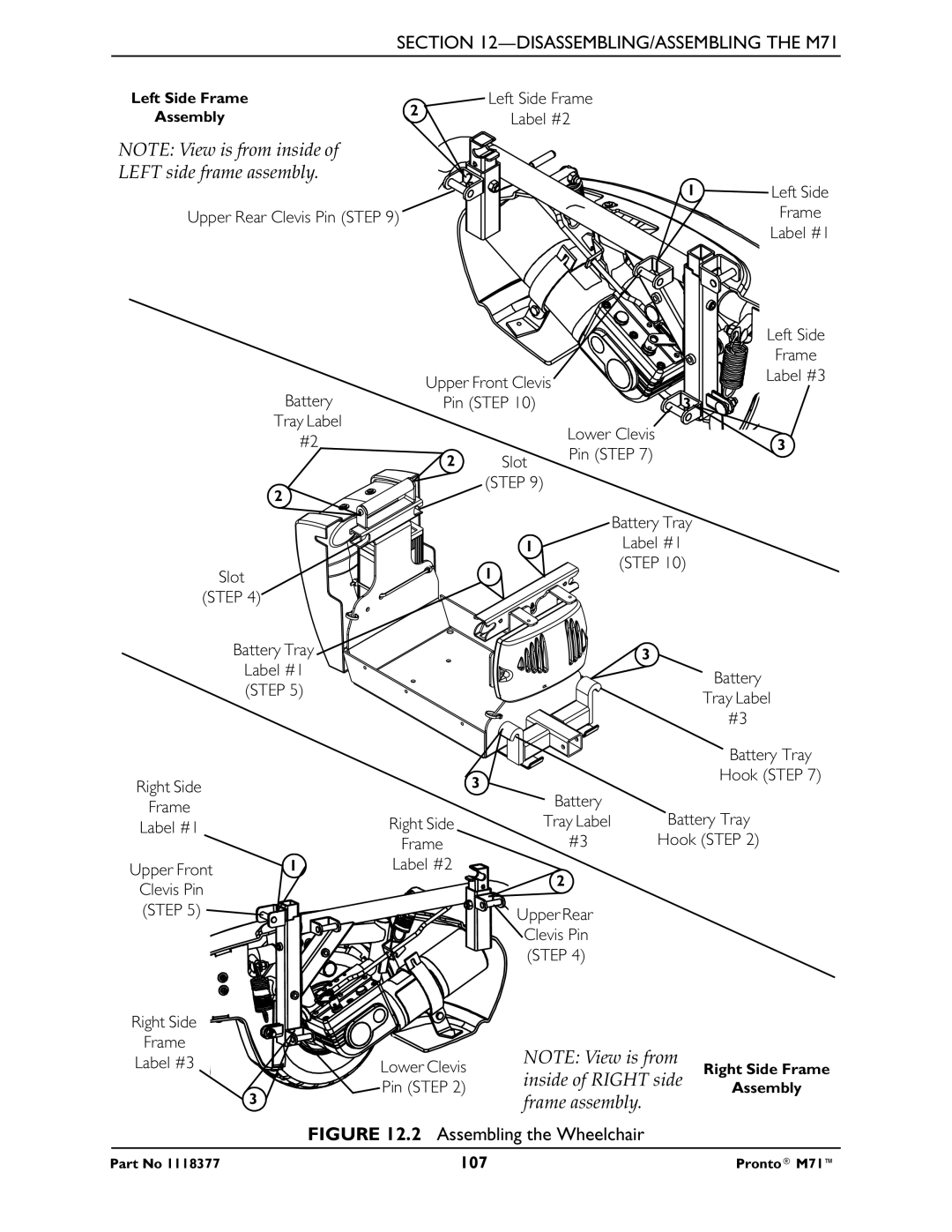
FIGURE 12.2 Assembling the Wheelchair
Part No 1118377 | 107 | Pronto® M71™ |
