SECTION 7—FRONT RIGGINGS/FOOTBOARD
NOTE: When installing the front rigging support tubes, ensure that the hinge pins are on the outside of the chair facing away from the seat frame.
1.Remove the seat assembly. Refer to Removing/Installing the Seat Assembly on page 30.
2.Remove the two socket bolts, spacers and locknuts that secure telescoping front rigging support to the seat frame.
3.Perform one of the following:
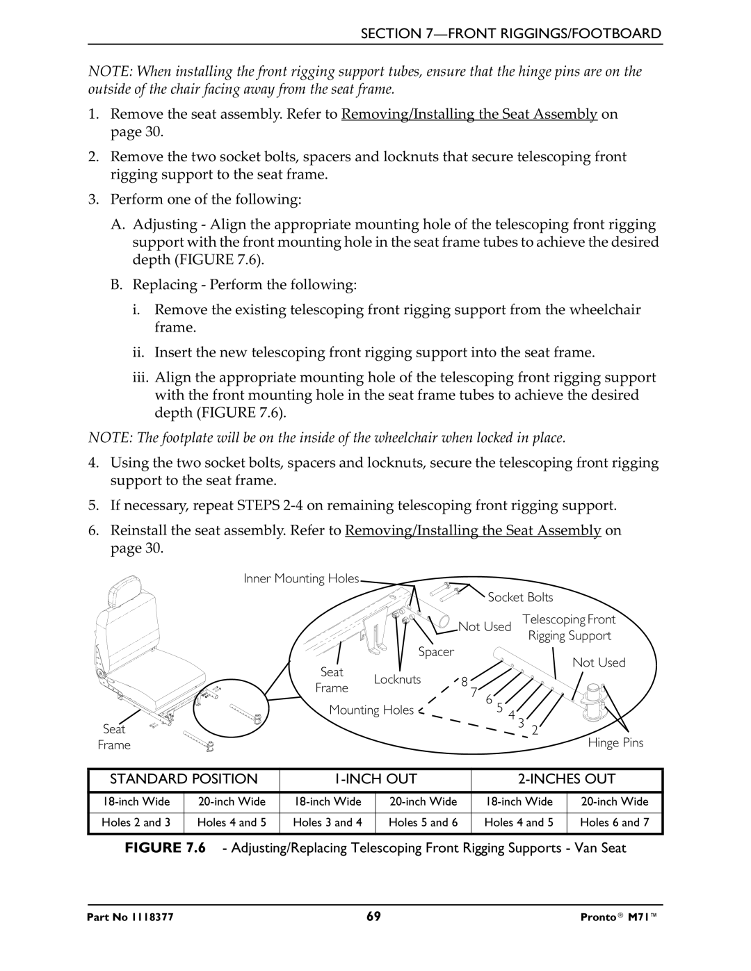
A.Adjusting - Align the appropriate mounting hole of the telescoping front rigging support with the front mounting hole in the seat frame tubes to achieve the desired depth (FIGURE 7.6).
B.Replacing - Perform the following:
i.Remove the existing telescoping front rigging support from the wheelchair frame.
ii.Insert the new telescoping front rigging support into the seat frame.
iii.Align the appropriate mounting hole of the telescoping front rigging support with the front mounting hole in the seat frame tubes to achieve the desired depth (FIGURE 7.6).
NOTE: The footplate will be on the inside of the wheelchair when locked in place.
4.Using the two socket bolts, spacers and locknuts, secure the telescoping front rigging support to the seat frame.
5.If necessary, repeat STEPS
6.Reinstall the seat assembly. Refer to Removing/Installing the Seat Assembly on page 30.
Inner Mounting Holes |
|
|
|
|
|
|
|
| Socket Bolts | ||
|
| Not Used | Telescoping Front | ||
|
|
|
|
| Rigging Support |
| Spacer |
|
|
| Not Used |
Seat |
|
|
|
| |
Locknuts | 8 |
|
|
| |
Frame |
|
|
| ||
| 7 | 6 |
|
| |
|
|
|
| ||
Mounting Holes |
| 5 | 4 3 2 | ||
Seat |
|
|
| ||
Frame |
|
|
|
| Hinge Pins |
STANDARD POSITION |
|
| |||
|
|
|
|
|
|
|
|
|
|
|
|
Holes 2 and 3 | Holes 4 and 5 | Holes 3 and 4 | Holes 5 and 6 | Holes 4 and 5 | Holes 6 and 7 |
|
|
|
|
|
|
FIGURE 7.6 - Adjusting/Replacing Telescoping Front Rigging Supports - Van Seat
Part No 1118377 | 69 | Pronto® M71™ |