SECTION 12—DISASSEMBLING/ASSEMBLING THE M71
Left Side Frame | 2 | |
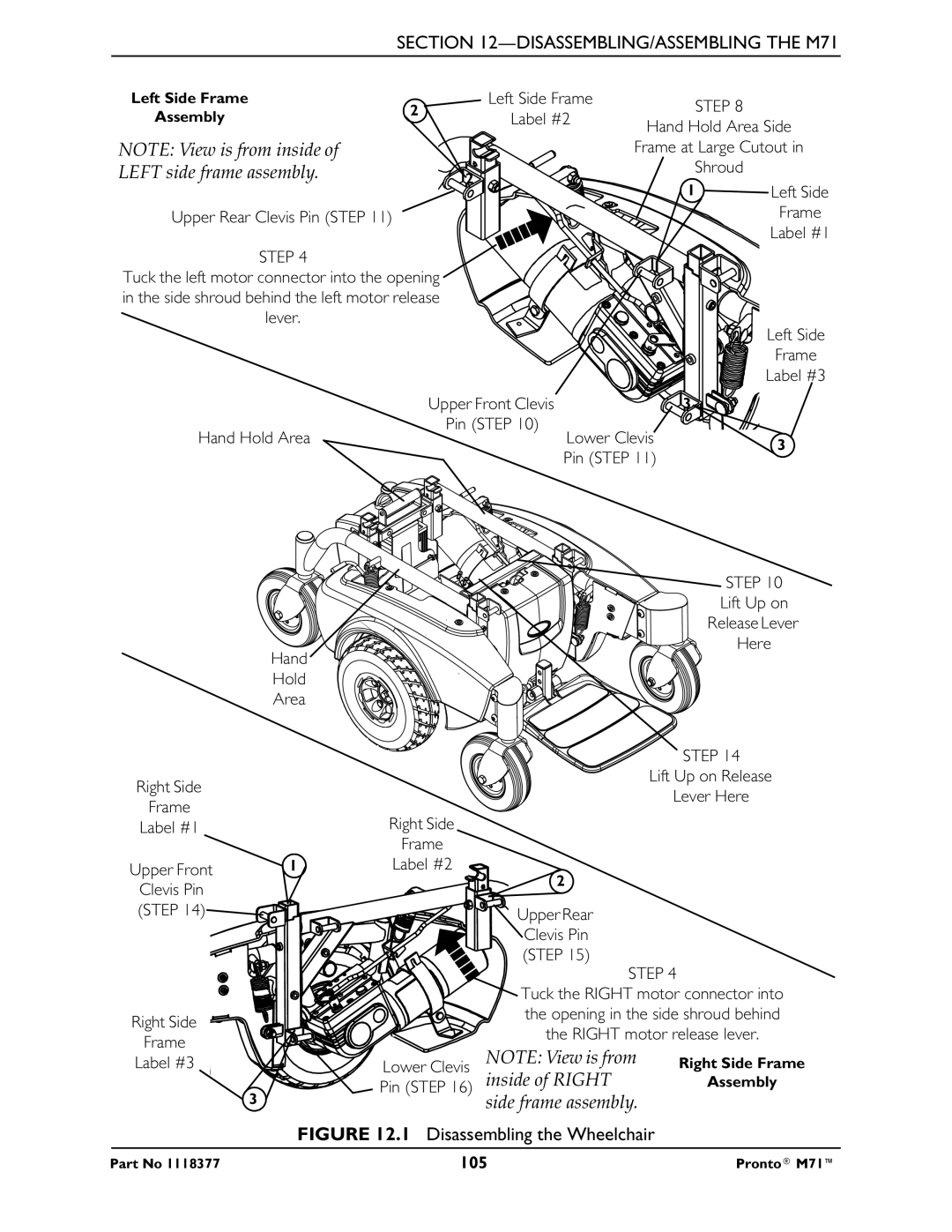
Assembly | ||
|
NOTE: View is from inside of
LEFT side frame assembly.
Upper Rear Clevis Pin (STEP 11) ![]()
STEP 4
Tuck the left motor connector into the opening ![]() in the side shroud behind the left motor release
in the side shroud behind the left motor release ![]() lever.
lever.
Left Side Frame | STEP 8 | |
Label #2 | ||
Hand Hold Area Side | ||
| ||
| Frame at Large Cutout in | |
| Shroud |
![]() 2
2
![]() 1
1 ![]()
![]() Left Side
Left Side
1Frame
Label #1
![]() 1
1
Left Side
Frame
Label #3
Upper Front Clevis |
| 3 |
Pin (STEP 10) |
|
|
Hand Hold Area | Lower Clevis | 3 |
|
|
Pin (STEP 11)
Hand![]()
Hold
Area
Right Side
Frame
Label #1
Upper Front | 1 |
Clevis Pin (STEP 14)![]()
![]()
Right Side
Frame
Label #3
![]() 3
3 ![]()
![]()
![]()
![]()
![]()
![]() STEP 10
STEP 10
Lift Up on
Release Lever Here
![]() STEP 14
STEP 14
Lift Up on Release
Lever Here
Right Side
Frame
Label #2
2
Upper Rear
![]() Clevis Pin (STEP 15)
Clevis Pin (STEP 15)
STEP 4
![]() Tuck the RIGHT motor connector into the opening in the side shroud behind the RIGHT motor release lever.
Tuck the RIGHT motor connector into the opening in the side shroud behind the RIGHT motor release lever.
Lower Clevis | NOTE: View is from | Right Side Frame |
Pin (STEP 16) | inside of RIGHT | Assembly |
| side frame assembly. |
|
FIGURE 12.1 Disassembling the Wheelchair
Part No 1118377 | 105 | Pronto® M71™ |