SECTION 10—BATTERIES/CHARGER
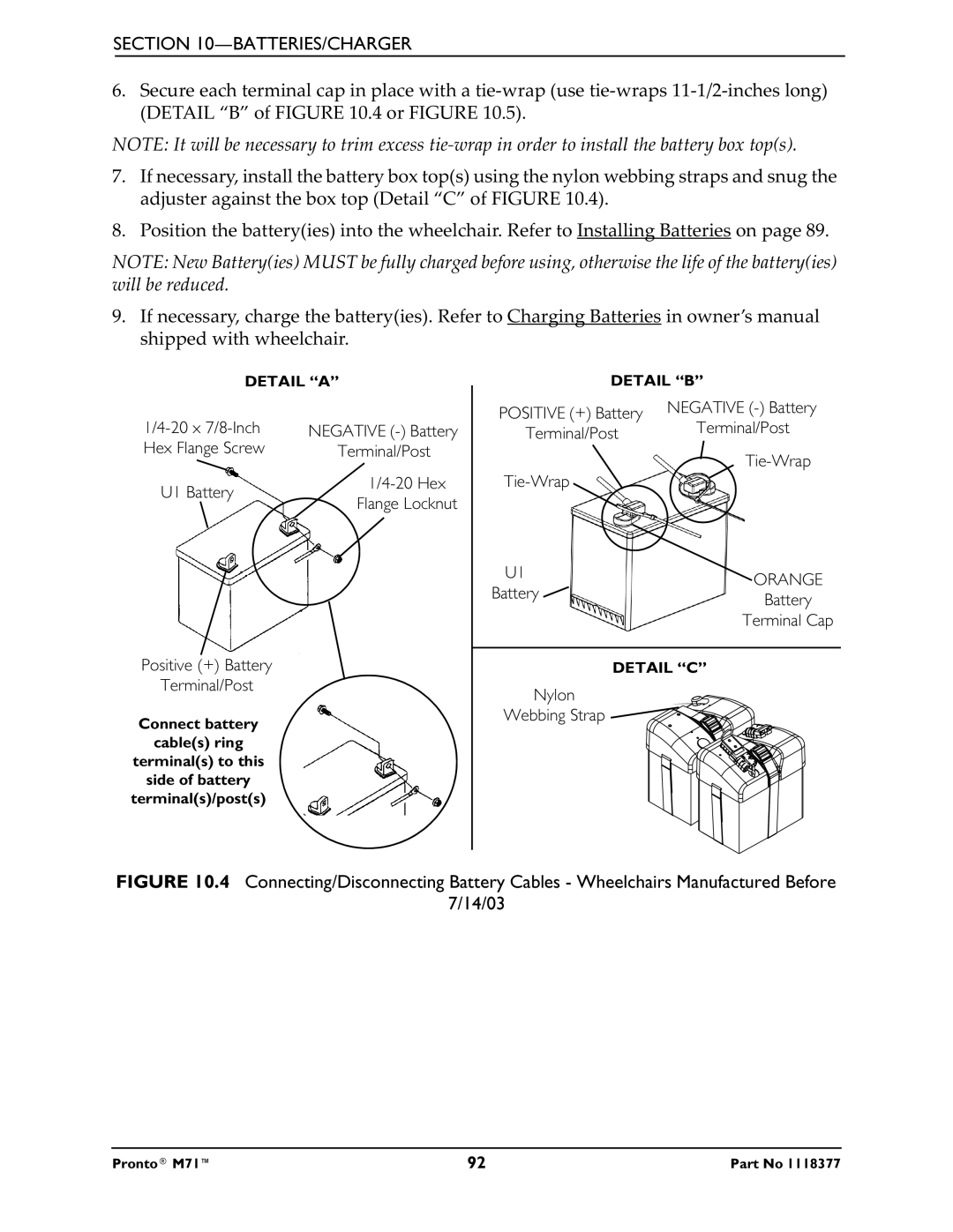
6.Secure each terminal cap in place with a
NOTE: It will be necessary to trim excess
7.If necessary, install the battery box top(s) using the nylon webbing straps and snug the adjuster against the box top (Detail “C” of FIGURE 10.4).
8.Position the battery(ies) into the wheelchair. Refer to Installing Batteries on page 89.
NOTE: New Battery(ies) MUST be fully charged before using, otherwise the life of the battery(ies) will be reduced.
9.If necessary, charge the battery(ies). Refer to Charging Batteries in owner’s manual shipped with wheelchair.
DETAIL “A”
| NEGATIVE | |
Hex Flange Screw | Terminal/Post | |
U1 Battery | ||
Flange Locknut | ||
|
Positive (+) Battery
Terminal/Post
Connect battery
cable(s) ring
terminal(s) to this
side of battery
terminal(s)/post(s)
| DETAIL “B” | ||
POSITIVE (+) Battery | NEGATIVE | ||
Terminal/Post | |||
Terminal/Post | |||
| |||
|
| ||
|
| ||
U1 |
| ORANGE | |
Battery |
| ||
| Battery | ||
|
| ||
|
| Terminal Cap | |
| DETAIL “C” | ||
Nylon |
|
| |
Webbing Strap |
|
| |
FIGURE 10.4 Connecting/Disconnecting Battery Cables - Wheelchairs Manufactured Before
7/14/03
Pronto® M71™ | 92 | Part No 1118377 |