2.4 RJ45 Ports – Signal Description
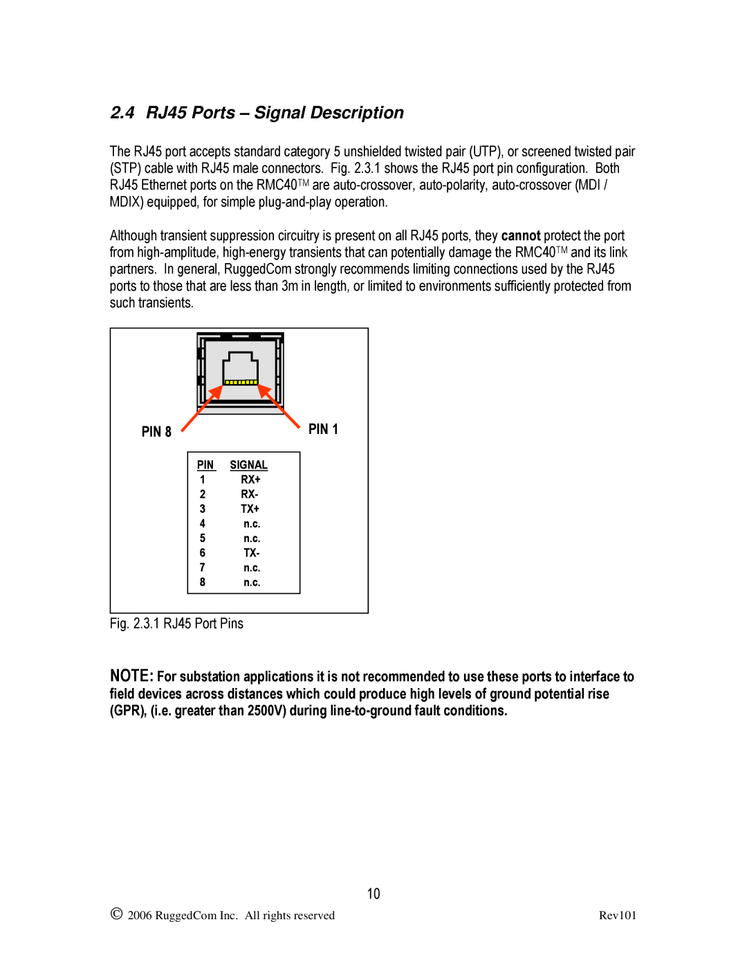
The RJ45 port accepts standard category 5 unshielded twisted pair (UTP), or screened twisted pair (STP) cable with RJ45 male connectors. Fig. 2.3.1 shows the RJ45 port pin configuration. Both RJ45 Ethernet ports on the RMC40TM are
Although transient suppression circuitry is present on all RJ45 ports, they cannot protect the port from
PIN 8 | PIN 1 |
PIN SIGNAL
1RX+
2RX-
3TX+
4n.c.
5n.c.
6TX-
7n.c.
8n.c.
Fig. 2.3.1 RJ45 Port Pins
NOTE: For substation applications it is not recommended to use these ports to interface to field devices across distances which could produce high levels of ground potential rise (GPR), (i.e. greater than 2500V) during
10
2006 RuggedCom Inc. All rights reserved | Rev101 |