
VX-2000d specifications
The Runco VX-2000d is a premium home theater projector that combines cutting-edge technology with a commitment to delivering extraordinary image quality. Renowned among enthusiasts for its exceptional performance, the VX-2000d caters to both the casual viewer and the most discerning cinephile, making it a standout option in the world of home entertainment.One of the primary features of the Runco VX-2000d is its native 1080p resolution, which ensures that images are crisp, detailed, and vibrant. With a resolution of 1920 x 1080 pixels, this projector capitalizes on High Definition content, enabling viewers to experience movies and shows as the directors intended. Coupled with high brightness levels and a remarkable contrast ratio, the VX-2000d exhibits deep blacks and brilliant colors, enhancing the overall viewing experience.
The VX-2000d incorporates advanced DLP (Digital Light Processing) technology that provides remarkable color accuracy and consistency across a variety of content. The use of the latest imaging chips and sophisticated optics creates lifelike imagery that draws viewers into the action. Additionally, this projector supports a wide color gamut, allowing it to reproduce a broader range of colors for enhanced realism.
Another highlight of the Runco VX-2000d is its sophisticated lens system. The projector features a high-quality glass lens that minimizes optical distortion while ensuring sharp focus across the entire image. Its motorized lens shift, zoom, and focus functionalities allow for easy installation and flexibility in positioning the projector within various home theater setups.
The VX-2000d also supports various video formats, including 24p film and 1080p/60, making it versatile for different types of content. Also, with its built-in proprietary video processing technology, the projector upscales standard-definition and high-definition content to optimized viewing experiences.
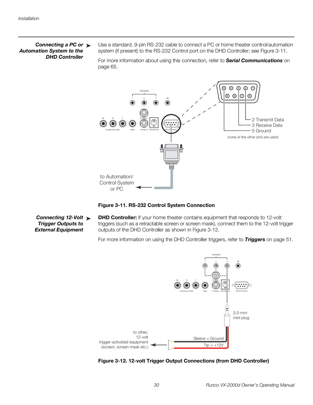
Furthermore, the Runco VX-2000d is equipped with a range of connectivity options, including HDMI, Component, and VGA inputs, ensuring compatibility with numerous devices such as Blu-ray players, gaming consoles, and streaming devices.
With its combination of excellent build quality, robust performance, and impressive features, the Runco VX-2000d remains a top choice for enthusiasts seeking an unparalleled home theater experience. Whether enjoying action-packed films or serene nature documentaries, this projector immerses viewers in a cinematic journey that captivates the senses.