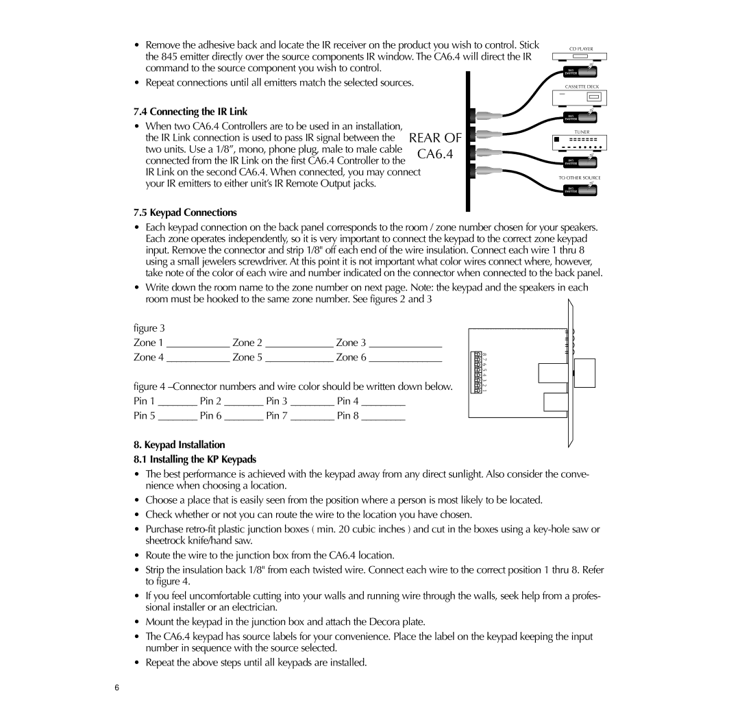
•Remove the adhesive back and locate the IR receiver on the product you wish to control. Stick the 845 emitter directly over the source components IR window. The CA6.4 will direct the IR command to the source component you wish to control.
•Repeat connections until all emitters match the selected sources.
7.4 Connecting the IR Link
•When two CA6.4 Controllers are to be used in an installation,
the IR Link connection is used to pass IR signal between the REAR OF | ||
two units. Use a 1/8”, mono, phone plug, male to male cable | CA6.4 | |
connected from the IR Link on the first CA6.4 Controller to the | ||
| ||
IR Link on the second CA6.4. When connected, you may connect | ||
your IR emitters to either unit’s IR Remote Output jacks. |
| |
7.5 Keypad Connections |
| |
CD PLAYER
845
EMITTER
CASSETTE DECK
845
EMITTER ![]()
TUNER
845
EMITTER
TO OTHER SOURCE
845
EMITTER
1584
DUAL
EMITTER
•Each keypad connection on the back panel corresponds to the room / zone number chosen for your speakers. Each zone operates independently, so it is very important to connect the keypad to the correct zone keypad input. Remove the connector and strip 1/8" off each end of the wire insulation. Connect each wire 1 thru 8 using a small jewelers screwdriver. At this point it is not important what color wires connect where, however, take note of the color of each wire and number indicated on the connector when connected to the back panel.
•Write down the room name to the zone number on next page. Note: the keypad and the speakers in each room must be hooked to the same zone number. See figures 2 and 3
figure 3
Zone 1 _____________ Zone 2 ______________ Zone 3 _______________
Zone 4 _____________ Zone 5 ______________ Zone 6 _______________
figure 4 –Connector numbers and wire color should be written down below. Pin 1 ________ Pin 2 ________ Pin 3 _________ Pin 4 _________
Pin 5 ________ Pin 6 ________ Pin 7 _________ Pin 8 _________
![]()
![]()
![]()
![]()
![]() 8 7 6 5 4 3 2 1
8 7 6 5 4 3 2 1
8. Keypad Installation
8.1 Installing the KP Keypads
•The best performance is achieved with the keypad away from any direct sunlight. Also consider the conve- nience when choosing a location.
•Choose a place that is easily seen from the position where a person is most likely to be located.
•Check whether or not you can route the wire to the location you have chosen.
•Purchase
•Route the wire to the junction box from the CA6.4 location.
•Strip the insulation back 1/8" from each twisted wire. Connect each wire to the correct position 1 thru 8. Refer to figure 4.
•If you feel uncomfortable cutting into your walls and running wire through the walls, seek help from a profes- sional installer or an electrician.
•Mount the keypad in the junction box and attach the Decora plate.
•The CA6.4 keypad has source labels for your convenience. Place the label on the keypad keeping the input number in sequence with the source selected.
•Repeat the above steps until all keypads are installed.
6
