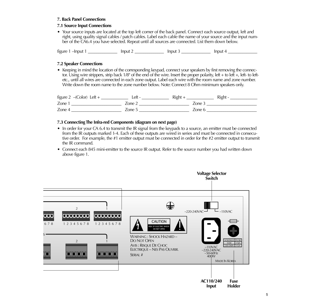
7.Back Panel Connections 7.1 Source Input Connections
•Your source inputs are located at the top left corner of the back panel. Connect each source output, left and right, using quality signal cables / patch cables. Label each cable the name of your source and the input num- ber of the CA6.4 you have selected. Repeat until all sources are connected. List them down below.
figure 1 –Input 1 ______________ Input 2 ______________ Input 3 ______________ Input 4 ______________
7.2 Speaker Connections
•Keeping in mind the location of the corresponding keypad, connect your speakers by first removing the connec- tor. Using wire strippers, strip back 1/8" of the end of the wire. Insert the proper polarity, left + to left +, left- to left- etc., until all wires are connected in each zone output. Label each wire with the room name and zone number.
Write down the room name to the zone number below. Note: Connect 8 Ohm minimum speakers only.
figure 2 –(Color) Left + _____________ Left - _____________ Right + _____________ Right - _____________
Zone 1 ________________________ Zone 2 ________________________ Zone 3 ________________________
Zone 4 ________________________ Zone 5 ________________________ Zone 6 ________________________
7.3 Connecting The Infra-red Components (diagram on next page)
•In order for your CA 6.4 to transmit the IR signal from the keypads to a source, an emitter must be connected from the IR outputs marked
•Connect each 845
Voltage Selector
Switch
| 2 | 1 |
6 7 8 | 1 2 3 4 5 6 7 8 | 1 2 3 4 5 6 7 8 |
~110VAC |
S |
|
|
|
|
| WARNING : SHOCK HAZARD – |
| ||||||
|
|
|
|
|
|
|
|
|
|
|
|
| |
2 |
|
| 1 |
|
| DO NOT OPEN |
| ||||||
|
|
|
|
|
|
|
|
|
|
|
| AVIS : RISQUE DE CHOC | ~110VAC |
|
|
|
|
|
|
|
|
|
|
| |||
|
|
|
|
|
|
|
|
|
|
| |||
|
|
|
|
|
|
|
|
|
|
|
| ELECTRIQUE – NES PAS OUVRIR. | |
|
|
|
|
|
|
|
|
|
|
|
| SERIAL # | |
|
|
|
|
|
|
|
|
|
|
|
| 400W | |
|
|
|
|
|
|
|
|
|
|
| |||
VOLTAGE FUSE
110V F4A
MADE IN KOREA
AC110/240 Fuse
Input Holder
5
