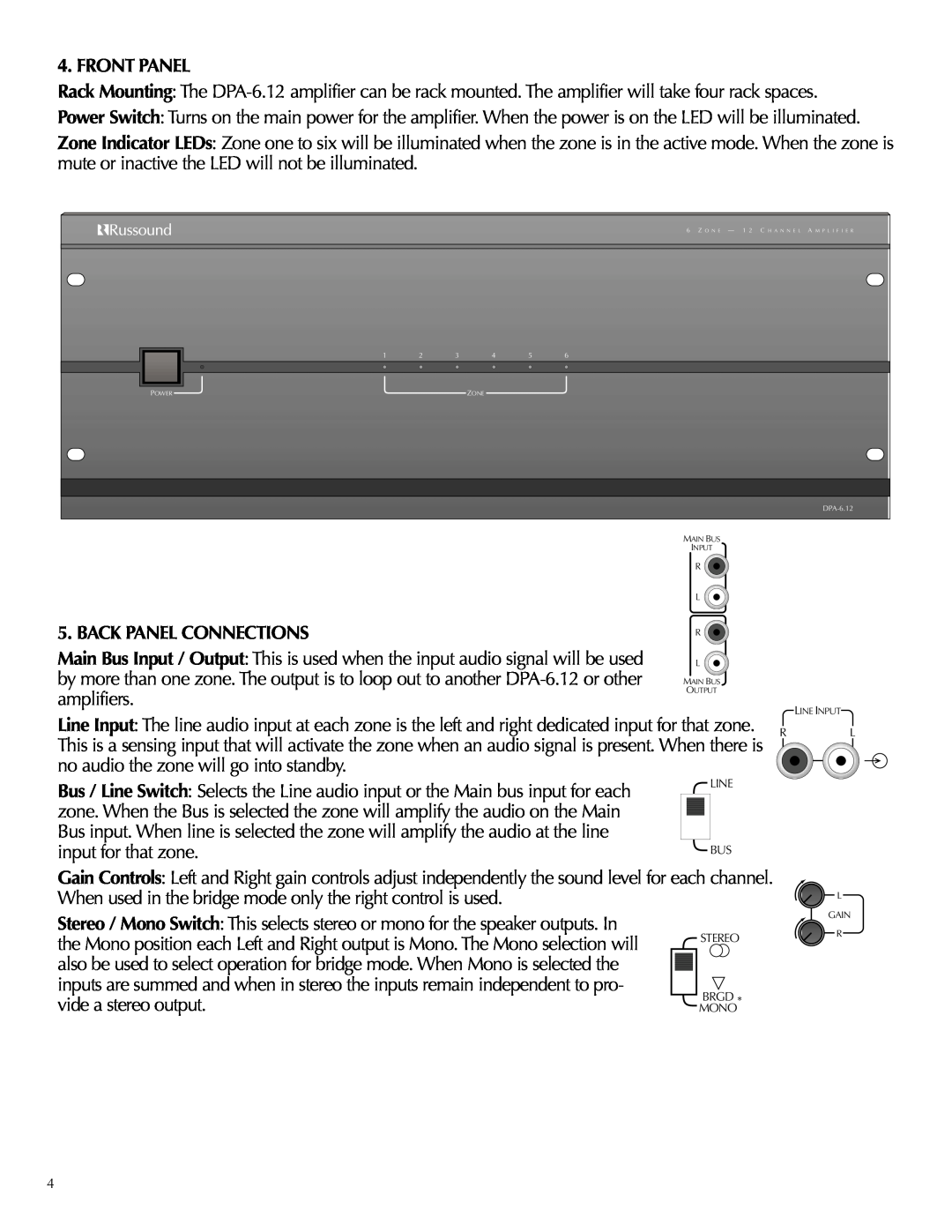
4. FRONT PANEL
Rack Mounting: The
Power Switch: Turns on the main power for the amplifier. When the power is on the LED will be illuminated.
Zone Indicator LEDs: Zone one to six will be illuminated when the zone is in the active mode. When the zone is mute or inactive the LED will not be illuminated.
|
|
|
|
| 6 Z O N E — 1 2 C H A N N E L A M P L I F I E R |
1 | 2 | 3 | 4 | 5 | 6 |
POWER |
|
| ZONE |
|
|
|
|
|
|
|
5. BACK PANEL CONNECTIONS
Main Bus Input / Output: This is used when the input audio signal will be used by more than one zone. The output is to loop out to another
MAIN BUS
INPUT
R
L
R
L
MAIN BUS
OUTPUT
LINE INPUT
Line Input: The line audio input at each zone is the left and right dedicated input for that zone. R This is a sensing input that will activate the zone when an audio signal is present. When there is no audio the zone will go into standby.
Bus / Line Switch: Selects the Line audio input or the Main bus input for each |
|
| LINE | |
zone. When the Bus is selected the zone will amplify the audio on the Main |
|
|
|
|
|
|
|
| |
Bus input. When line is selected the zone will amplify the audio at the line |
|
|
|
|
input for that zone. |
|
| BUS | |
Gain Controls: Left and Right gain controls adjust independently the sound level for each channel. When used in the bridge mode only the right control is used.
Stereo / Mono Switch: This selects stereo or mono for the speaker outputs. In
the Mono position each Left and Right output is Mono. The Mono selection will |
|
|
| STEREO | |
also be used to select operation for bridge mode. When Mono is selected the |
|
|
|
| |
|
|
|
| ||
inputs are summed and when in stereo the inputs remain independent to pro- |
|
|
| BRGD | |
vide a stereo output. | |||||
MONO* | |||||
L
L
GAIN
R
4