ROUTER MOUNTING (Cont'd)
TO ASSEMBLE TABLE CLAMPING BRACKET (Cont'd)
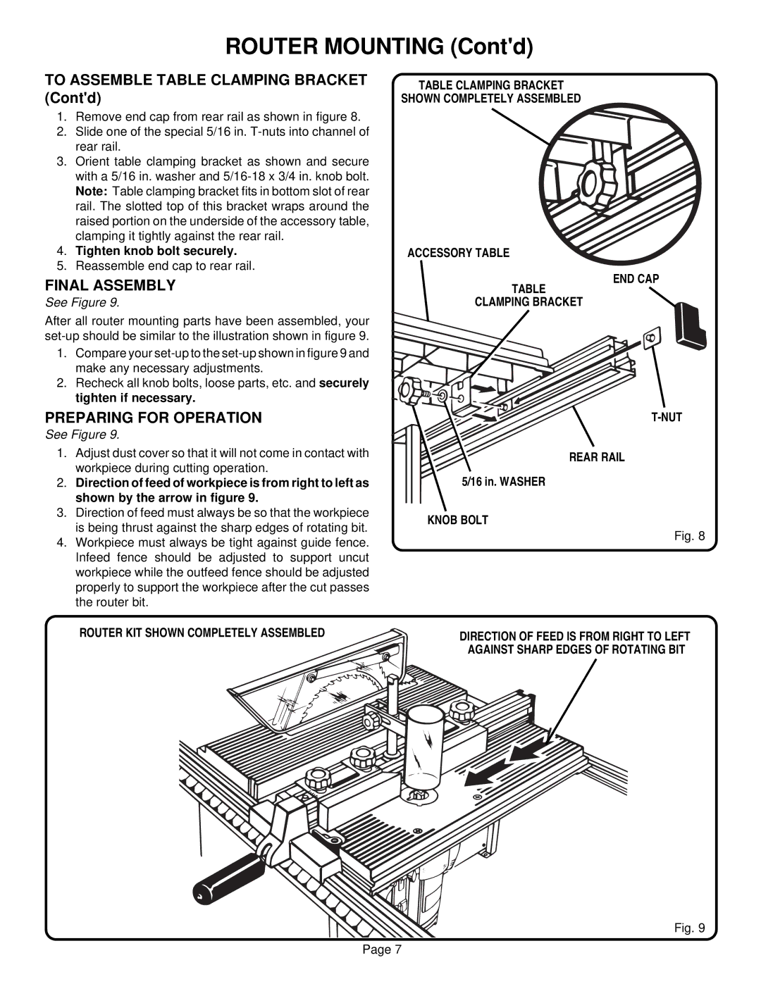
1.Remove end cap from rear rail as shown in figure 8.
2.Slide one of the special 5/16 in.
3.Orient table clamping bracket as shown and secure with a 5/16 in. washer and
4.Tighten knob bolt securely.
5.Reassemble end cap to rear rail.
FINAL ASSEMBLY
See Figure 9.
After all router mounting parts have been assembled, your
1.Compare your
2.Recheck all knob bolts, loose parts, etc. and securely tighten if necessary.
PREPARING FOR OPERATION
See Figure 9.
1.Adjust dust cover so that it will not come in contact with workpiece during cutting operation.
2.Direction of feed of workpiece is from right to left as shown by the arrow in figure 9.
3.Direction of feed must always be so that the workpiece is being thrust against the sharp edges of rotating bit.
4.Workpiece must always be tight against guide fence. Infeed fence should be adjusted to support uncut workpiece while the outfeed fence should be adjusted properly to support the workpiece after the cut passes the router bit.
ROUTER KIT SHOWN COMPLETELY ASSEMBLED
TABLE CLAMPING BRACKET
SHOWN COMPLETELY ASSEMBLED
ACCESSORY TABLE
END CAP
TABLE
CLAMPING BRACKET
REAR RAIL
5/16 in. WASHER
KNOB BOLT
Fig. 8
DIRECTION OF FEED IS FROM RIGHT TO LEFT
AGAINST SHARP EDGES OF ROTATING BIT
Fig. 9
Page 7