ASSEMBLY
Read these instructions completely before beginning assembly of this kit.
ROUTER MOUNTING
![]() WARNING:
WARNING:
The saw's motor cord must be disconnected from the receptacle provided on the saw when using this kit with a Router or Jig Saw mounted to the accessory table. The power supply cord of the Router or Jig Saw must be plugged into the receptacle and the saw's master switch must be used to turn the Router or Jig Saw "ON" or "OFF".
IMPORTANT
This router kit has been specifically designed for use with the Ryobi Model RE600 Electronic Router Only. The hole pattern on the mounting plate has not been drilled to accommodate other routers on the market. Special mounting screws are provided with the RE600 to insure safe, secure mounting.
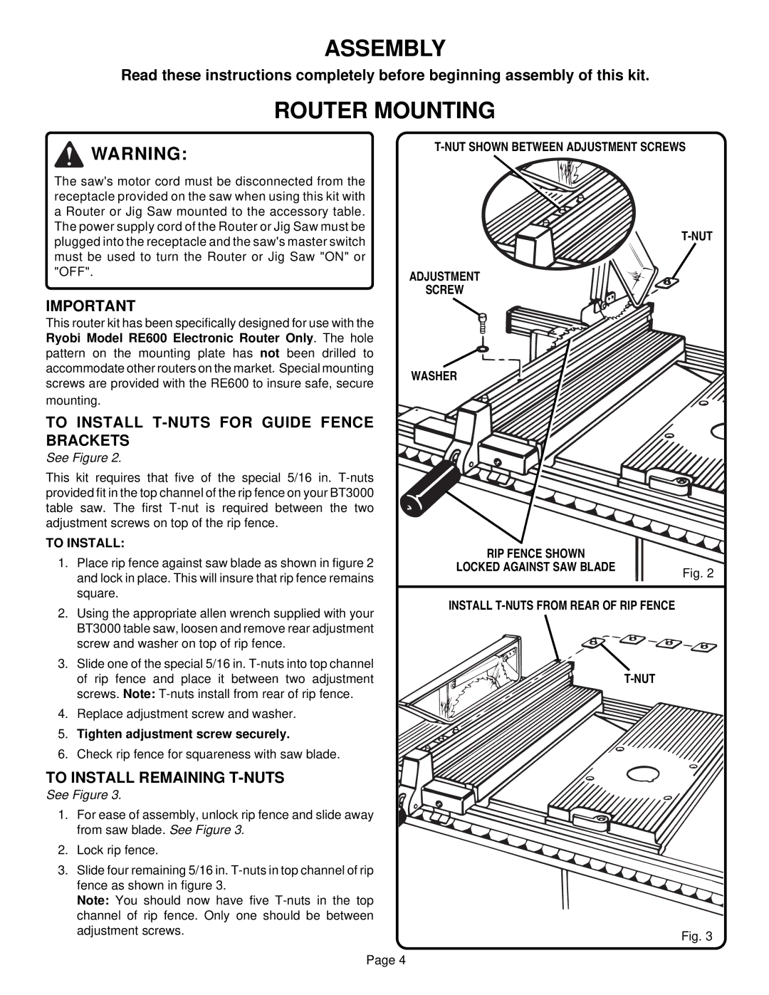
TO INSTALL T-NUTS FOR GUIDE FENCE BRACKETS
See Figure 2.
This kit requires that five of the special 5/16 in.
TO INSTALL:
1.Place rip fence against saw blade as shown in figure 2 and lock in place. This will insure that rip fence remains square.
2.Using the appropriate allen wrench supplied with your BT3000 table saw, loosen and remove rear adjustment screw and washer on top of rip fence.
3.Slide one of the special 5/16 in.
4.Replace adjustment screw and washer.
5.Tighten adjustment screw securely.
6.Check rip fence for squareness with saw blade.
ADJUSTMENT
SCREW
WASHER
RIP FENCE SHOWN |
|
LOCKED AGAINST SAW BLADE | Fig. 2 |
|
INSTALL
TO INSTALL REMAINING T-NUTS
See Figure 3.
1. For ease of assembly, unlock rip fence and slide away from saw blade. See Figure 3.
2. Lock rip fence.
3. Slide four remaining 5/16 in.
fence as shown in figure 3. |
|
Note: You should now have five |
|
channel of rip fence. Only one should be between |
|
adjustment screws. | Fig. 3 |
| |
Page 4 |
|