ADJUSTMENTS
WARNING:
Before performing any adjustment, make sure the tool is unplugged from the power supply and the switch is in the OFF position. Failure to heed this warning could result in serious personal injury.
BASE LOCKING LEVER ADJUSTMENT
See Figures 17 and 18.
The base locking lever may need occasional adjustment. It may be necessary to tighten the lever.
nUnplug the saw.
nIf attached, remove the vacuum attachment.
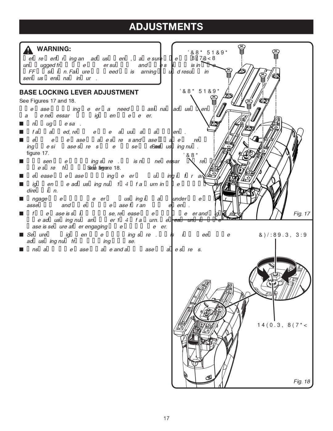
nRemove the base plate screws and base plate by remov- ing the six base screws to expose the adjusting nut. See figure 17.
nLoosen the locking screw. It is not necessary to remove the screw from the base. See figure 18.
nRelease the base locking lever by pulling it forward.
nTighten the adjusting nut 1/4 of a turn in the clockwise direction.
nEngage the lock lever by pushing it back under the motor assembly and check the base for any movement.
nIf the base is still loose, release the lock lever and tighten the adjusting nut another 1/4 of a turn. Repeat until the base is secure after engaging the lock lever.
nSecurely tighten the locking screw. This will keep the adjusting nut from coming loose.
nInstall the base plate and all base plate screws.
BASE PLATE
SCREWS
BASE PLATE
BASE
Fig. 17
ADJUSTING NUT
LOCKING SCREW
Fig. 18
17