OPERATION
TO ADJUST DEPTH OF CUT FOR PLUNGE BASE ROUTERS
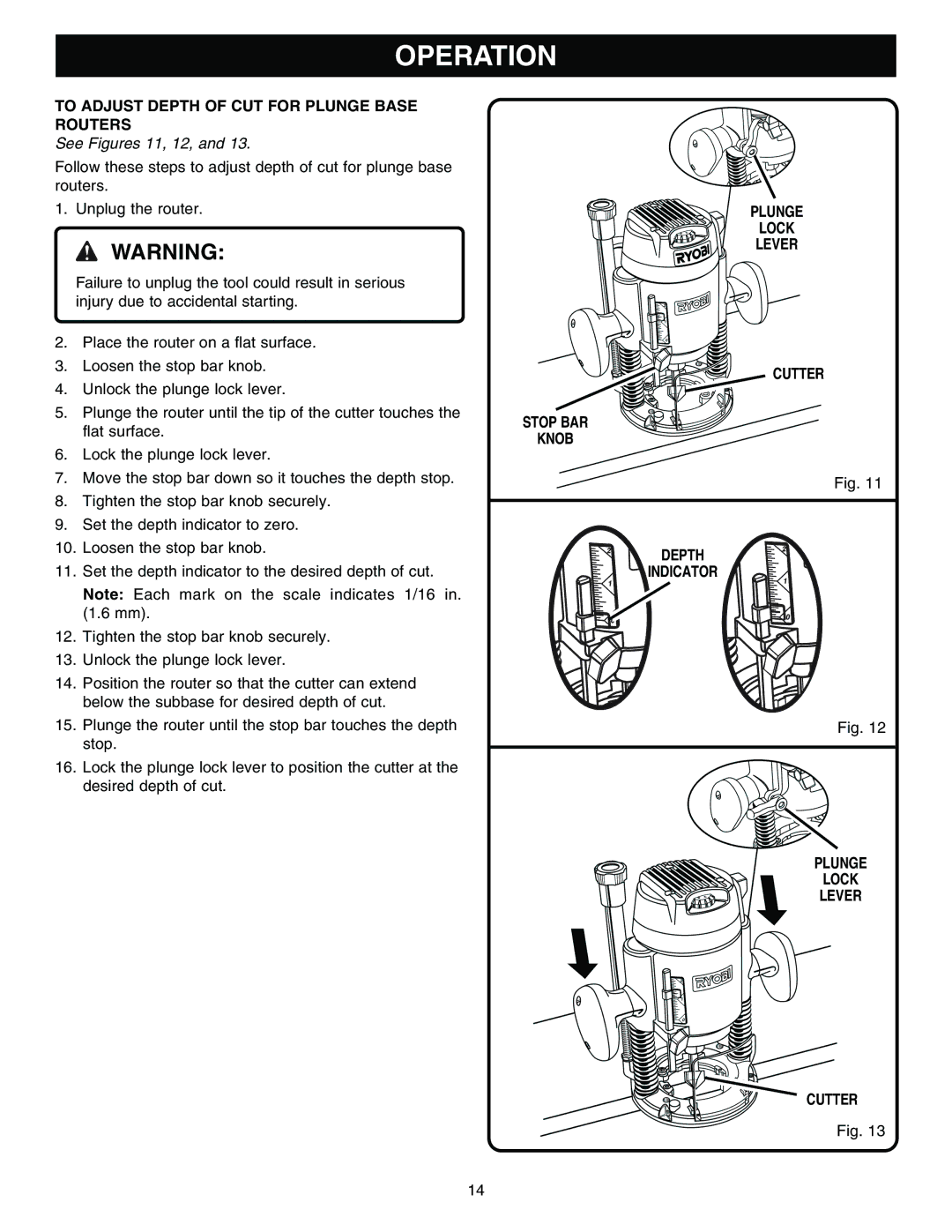
See Figures 11, 12, and 13.
Follow these steps to adjust depth of cut for plunge base routers.
1.Unplug the router.
![]() WARNING:
WARNING:
Failure to unplug the tool could result in serious injury due to accidental starting.
2.Place the router on a flat surface.
3.Loosen the stop bar knob.
4.Unlock the plunge lock lever.
5.Plunge the router until the tip of the cutter touches the flat surface.
6.Lock the plunge lock lever.
7.Move the stop bar down so it touches the depth stop.
8.Tighten the stop bar knob securely.
9.Set the depth indicator to zero.
10.Loosen the stop bar knob.
11.Set the depth indicator to the desired depth of cut.
Note: Each mark on the scale indicates 1/16 in. (1.6 mm).
12.Tighten the stop bar knob securely.
13.Unlock the plunge lock lever.
14.Position the router so that the cutter can extend below the subbase for desired depth of cut.
15.Plunge the router until the stop bar touches the depth stop.
16.Lock the plunge lock lever to position the cutter at the desired depth of cut.
PLUNGE
LOCK
LEVER
 CUTTER
STOP BAR
KNOB
Fig. 11
DEPTH
INDICATOR
Fig. 12
PLUNGE
LOCK
LEVER
![]() CUTTER
CUTTER
Fig. 13
14
