MAINTENANCE
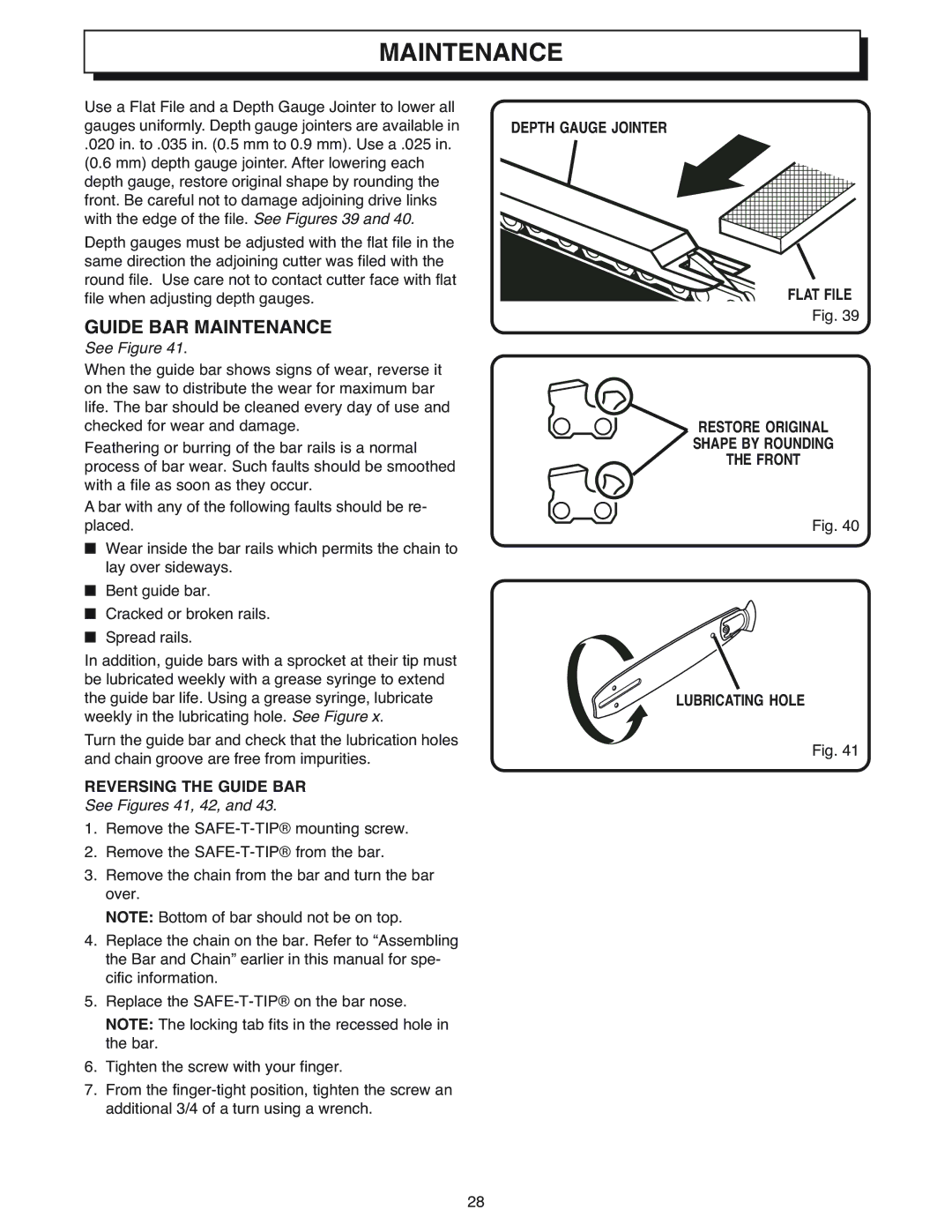
Use a Flat File and a Depth Gauge Jointer to lower all gauges uniformly. Depth gauge jointers are available in
.020 in. to .035 in. (0.5 mm to 0.9 mm). Use a .025 in. (0.6 mm) depth gauge jointer. After lowering each depth gauge, restore original shape by rounding the front. Be careful not to damage adjoining drive links with the edge of the file. See Figures 39 and 40.
Depth gauges must be adjusted with the flat file in the same direction the adjoining cutter was filed with the round file. Use care not to contact cutter face with flat file when adjusting depth gauges.
GUIDE BAR MAINTENANCE
See Figure 41.
When the guide bar shows signs of wear, reverse it on the saw to distribute the wear for maximum bar life. The bar should be cleaned every day of use and checked for wear and damage.
Feathering or burring of the bar rails is a normal process of bar wear. Such faults should be smoothed with a file as soon as they occur.
A bar with any of the following faults should be re- placed.
■Wear inside the bar rails which permits the chain to lay over sideways.
■Bent guide bar.
■Cracked or broken rails.
■Spread rails.
In addition, guide bars with a sprocket at their tip must be lubricated weekly with a grease syringe to extend the guide bar life. Using a grease syringe, lubricate weekly in the lubricating hole. See Figure x.
Turn the guide bar and check that the lubrication holes and chain groove are free from impurities.
REVERSING THE GUIDE BAR
See Figures 41, 42, and 43.
1.Remove the
2.Remove the
3.Remove the chain from the bar and turn the bar over.
NOTE: Bottom of bar should not be on top.
4.Replace the chain on the bar. Refer to “Assembling the Bar and Chain” earlier in this manual for spe- cific information.
5.Replace the
NOTE: The locking tab fits in the recessed hole in the bar.
6.Tighten the screw with your finger.
7.From the
28
DEPTH GAUGE JOINTER
FLAT FILE
Fig. 39
RESTORE ORIGINAL
SHAPE BY ROUNDING
THE FRONT
Fig. 40
LUBRICATING HOLE
Fig. 41