Guided Tour - Rear Panel
1 |
| 2 |
|
|
|
4
7
1
ENGLISH
PUSH TO RESET | OUTPUT |
|
|
| INPUT |
BRIDGE |
|
| PUSH | PUSH | |
20A / 250V | (8Ω~16Ω) |
|
| BALANCED | BALANCED |
|
|
| 0dBm | 0dBm | |
|
|
|
| ||
12 |
|
|
|
|
|
A |
|
|
|
|
|
M |
|
|
|
|
|
P |
|
|
| TRS |
|
|
|
|
| BALANCED |
|
| (4Ω~8Ω) | (4Ω~8Ω) |
| •TIP=HOT |
|
| •RING=COLD |
| |||
|
|
| •SLEEVE=GND |
| |
|
|
|
| XLR |
|
|
|
|
| BALANCED |
|
|
|
|
| •3=COLD |
|
|
|
|
| •2=HOT |
|
|
|
|
| •1=GND |
|
~AC INPUT | (4Ω~8Ω) | (4Ω~8Ω) | BRIDGED | PARALLEL |
|
CH 2 | CH 1 |
| STEREO | CH 1 | |
120V 60Hz, 770W |
| CH 2 | |||
|
|
|
|
|
|
|
|
|
|
|
|
|
|
|
|
|
|
|
|
3 |
| 5 |
| 6 |
|
| 8 |
| |
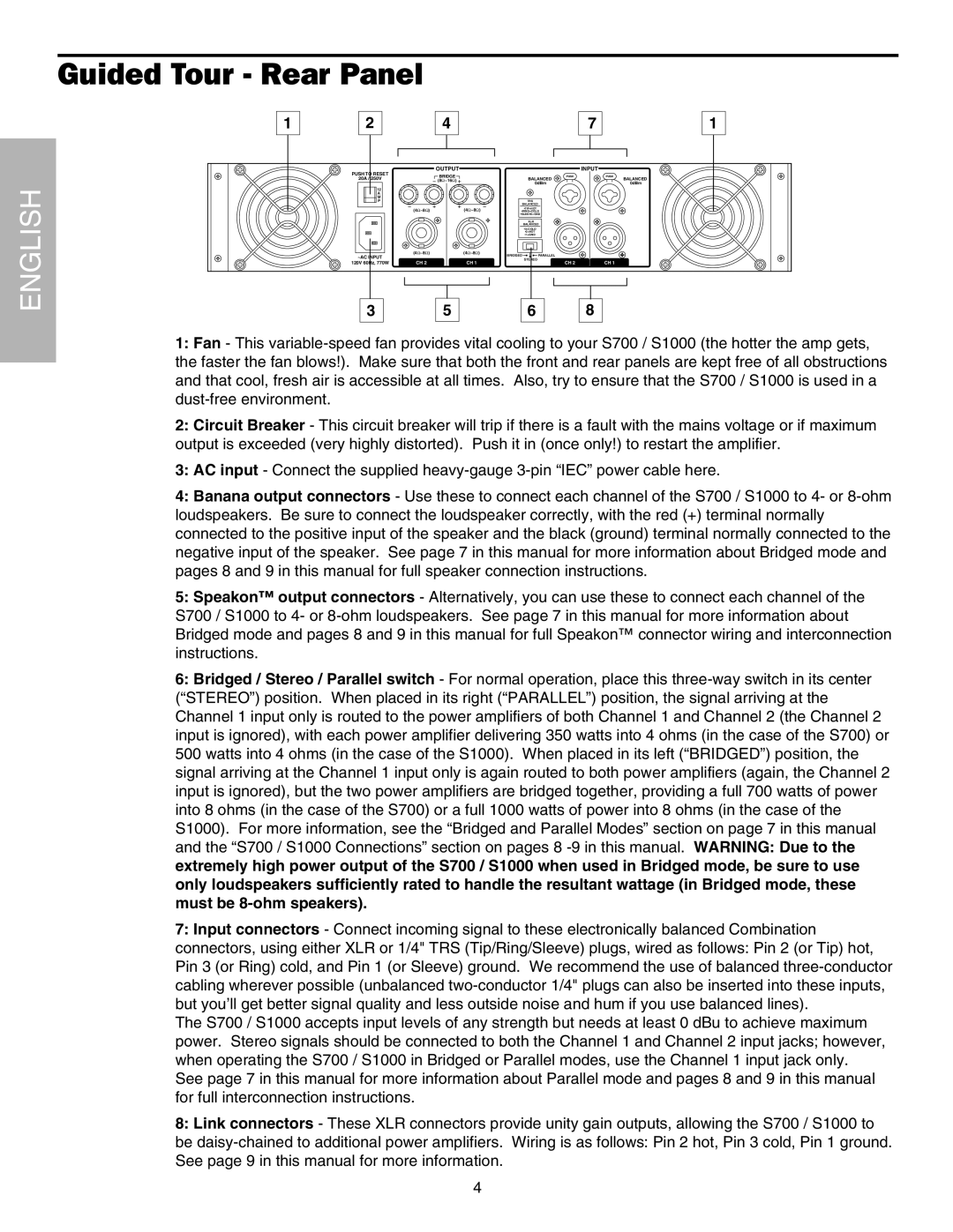
1:Fan - This
the faster the fan blows!). Make sure that both the front and rear panels are kept free of all obstructions and that cool, fresh air is accessible at all times. Also, try to ensure that the S700 / S1000 is used in a
2:Circuit Breaker - This circuit breaker will trip if there is a fault with the mains voltage or if maximum output is exceeded (very highly distorted). Push it in (once only!) to restart the amplifier.
3:AC input - Connect the supplied
4:Banana output connectors - Use these to connect each channel of the S700 / S1000 to 4- or
5:Speakon™ output connectors - Alternatively, you can use these to connect each channel of the S700 / S1000 to 4- or
6:Bridged / Stereo / Parallel switch - For normal operation, place this
(“STEREO”) position. When placed in its right (“PARALLEL”) position, the signal arriving at the Channel 1 input only is routed to the power amplifiers of both Channel 1 and Channel 2 (the Channel 2 input is ignored), with each power amplifier delivering 350 watts into 4 ohms (in the case of the S700) or 500 watts into 4 ohms (in the case of the S1000). When placed in its left (“BRIDGED”) position, the signal arriving at the Channel 1 input only is again routed to both power amplifiers (again, the Channel 2 input is ignored), but the two power amplifiers are bridged together, providing a full 700 watts of power into 8 ohms (in the case of the S700) or a full 1000 watts of power into 8 ohms (in the case of the S1000). For more information, see the “Bridged and Parallel Modes” section on page 7 in this manual and the “S700 / S1000 Connections” section on pages 8
7:Input connectors - Connect incoming signal to these electronically balanced Combination connectors, using either XLR or 1/4" TRS (Tip/Ring/Sleeve) plugs, wired as follows: Pin 2 (or Tip) hot, Pin 3 (or Ring) cold, and Pin 1 (or Sleeve) ground. We recommend the use of balanced
The S700 / S1000 accepts input levels of any strength but needs at least 0 dBu to achieve maximum power. Stereo signals should be connected to both the Channel 1 and Channel 2 input jacks; however, when operating the S700 / S1000 in Bridged or Parallel modes, use the Channel 1 input jack only.
See page 7 in this manual for more information about Parallel mode and pages 8 and 9 in this manual for full interconnection instructions.
8:Link connectors - These XLR connectors provide unity gain outputs, allowing the S700 / S1000 to
be
4