HEAT PUMP SPECIFICATIONS
G/VSZ130[18-60]1A*
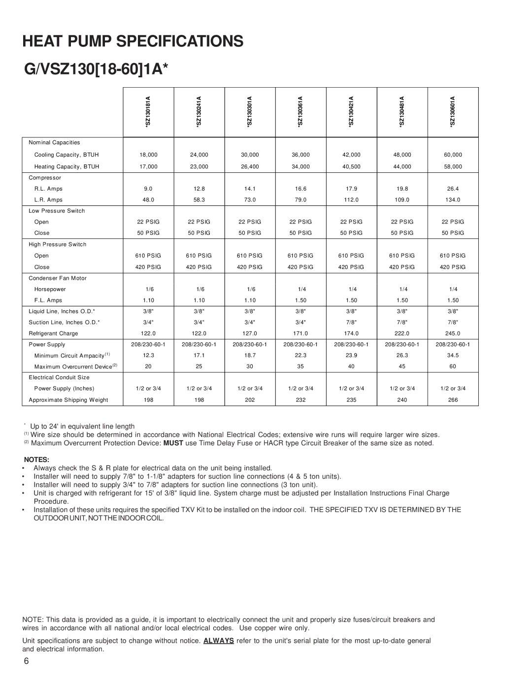
| *SZ130181A | *SZ130241A | *SZ130301A | *SZ130361A | *SZ130421A | *SZ130481A | *SZ130601A |
|
|
|
|
|
|
|
|
Nominal Capacities |
|
|
|
|
|
|
|
Cooling Capacity, BTUH | 18,000 | 24,000 | 30,000 | 36,000 | 42,000 | 48,000 | 60,000 |
Heating Capacity, BTUH | 17,000 | 23,000 | 26,400 | 34,000 | 40,500 | 44,000 | 58,000 |
|
|
|
|
|
|
|
|
Compressor |
|
|
|
|
|
|
|
R.L. Amps | 9.0 | 12.8 | 14.1 | 16.6 | 17.9 | 19.8 | 26.4 |
L.R. Amps | 48.0 | 58.3 | 73.0 | 79.0 | 112.0 | 109.0 | 134.0 |
|
|
|
|
|
|
|
|
Low Pressure Switch |
|
|
|
|
|
|
|
Open | 22 PSIG | 22 PSIG | 22 PSIG | 22 PSIG | 22 PSIG | 22 PSIG | 22 PSIG |
Close | 50 PSIG | 50 PSIG | 50 PSIG | 50 PSIG | 50 PSIG | 50 PSIG | 50 PSIG |
|
|
|
|
|
|
|
|
High Pressure Switch |
|
|
|
|
|
|
|
Open | 610 PSIG | 610 PSIG | 610 PSIG | 610 PSIG | 610 PSIG | 610 PSIG | 610 PSIG |
Close | 420 PSIG | 420 PSIG | 420 PSIG | 420 PSIG | 420 PSIG | 420 PSIG | 420 PSIG |
|
|
|
|
|
|
|
|
Condenser Fan Motor |
|
|
|
|
|
|
|
Horsepower | 1/6 | 1/6 | 1/6 | 1/4 | 1/4 | 1/4 | 1/4 |
F.L. Amps | 1.10 | 1.10 | 1.10 | 1.50 | 1.50 | 1.50 | 1.50 |
|
|
|
|
|
|
|
|
Liquid Line, Inches O.D.* | 3/8" | 3/8" | 3/8" | 3/8" | 3/8" | 3/8" | 3/8" |
Suction Line, Inches O.D.* | 3/4" | 3/4" | 3/4" | 3/4" | 7/8" | 7/8" | 7/8" |
Refrigerant Charge | 122.0 | 122.0 | 127.0 | 171.0 | 174.0 | 222.0 | 245.0 |
|
|
|
|
|
|
|
|
Power Supply | |||||||
Minimum Circuit Ampacity(1) | 12.3 | 17.1 | 18.7 | 22.3 | 23.9 | 26.3 | 34.5 |
Maximum Overcurrent Device(2) | 20 | 25 | 30 | 35 | 40 | 45 | 60 |
Electrical Conduit Size |
|
|
|
|
|
|
|
Power Supply (Inches) | 1/2 or 3/4 | 1/2 or 3/4 | 1/2 or 3/4 | 1/2 or 3/4 | 1/2 or 3/4 | 1/2 or 3/4 | 1/2 or 3/4 |
Approximate Shipping Weight | 198 | 198 | 202 | 232 | 235 | 240 | 266 |
|
|
|
|
|
|
|
|
*Up to 24' in equivalent line length
(1)Wire size should be determined in accordance with National Electrical Codes; extensive wire runs will require larger wire sizes.
(2)Maximum Overcurrent Protection Device: MUST use Time Delay Fuse or HACR type Circuit Breaker of the same size as noted.
NOTES:
•Always check the S & R plate for electrical data on the unit being installed.
•Installer will need to supply 7/8" to
•Installer will need to supply 3/4" to 7/8" adapters for suction line connections (3 ton unit).
•Unit is charged with refrigerant for 15' of 3/8" liquid line. System charge must be adjusted per Installation Instructions Final Charge Procedure.
•Installation of these units requires the specified TXV Kit to be installed on the indoor coil. THE SPECIFIED TXV IS DETERMINED BY THE OUTDOOR UNIT, NOT THE INDOOR COIL.
NOTE: This data is provided as a guide, it is important to electrically connect the unit and properly size fuses/circuit breakers and wires in accordance with all national and/or local electrical codes. Use copper wire only.
Unit specifications are subject to change without notice. ALWAYS refer to the unit's serial plate for the most
6