
X12D, X15D specifications
The Samson X15D and X12D represent a cutting-edge advancement in the world of wireless audio technology, designed primarily for musicians, sound engineers, and audio enthusiasts alike. Each model brings unique characteristics and features that enhance performance and user experience, making them vital tools for both live performances and studio settings.The Samson X15D is engineered for versatility and expansive sound. Boasting a robust 15-inch low-frequency driver, it delivers an impressive bass response, making it an ideal choice for genres that demand a deep, resonant sound. The built-in 2000-watt amplifier ensures that sound remains clear and powerful, even at high volumes. This model also features a 1.2-inch high-frequency driver that provides crisp treble, allowing vocals and instruments to shine through without being overshadowed by the bass.
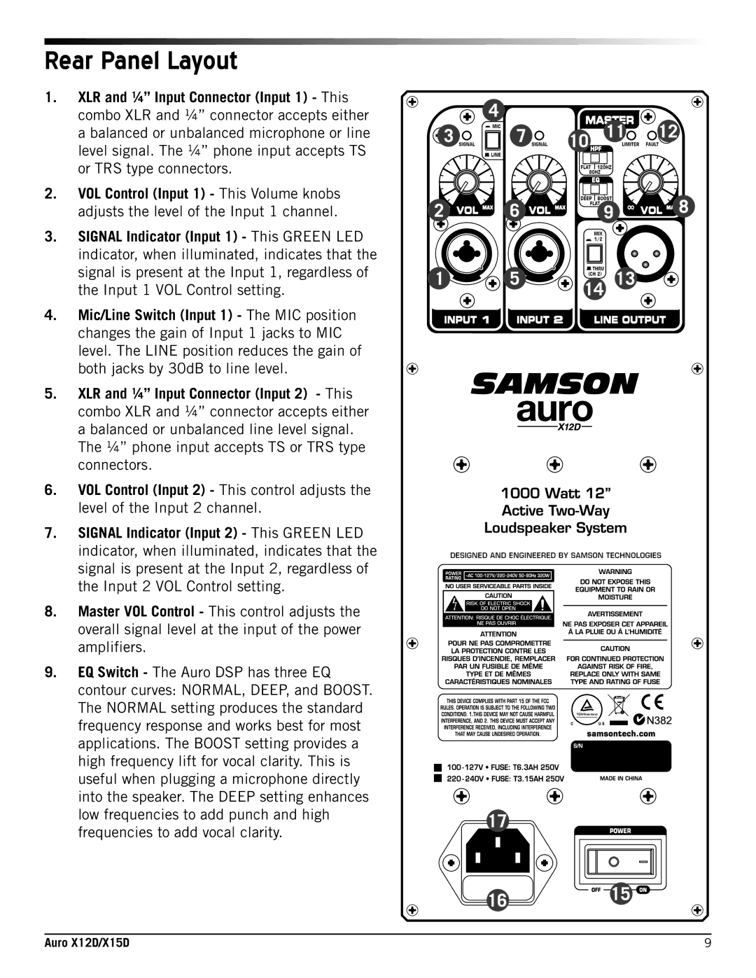
In contrast, the Samson X12D is tailored for users seeking a compact yet robust sound solution. With a 12-inch low-frequency driver, the X12D balances performance with portability, making it suitable for smaller venues or mobile setups. The 1000-watt amplifier delivers substantial power, ensuring that the sound maintains its integrity even in challenging acoustic environments. Both models provide an array of inputs and outputs, allowing for easy integration with various other audio equipment.
A standout feature of both X15D and X12D is the built-in digital signal processing (DSP). This technology helps to optimize the audio output by managing dynamics, equalization, and limiting, resulting in a cleaner sound. Users can take advantage of preset equalization settings, which can be easily adjusted to match the acoustics of the performance space.
Another noteworthy characteristic is their rugged construction, designed to withstand the rigors of transport and performance. The durable exterior not only ensures longevity but also helps to protect internal components during travel.
In summary, the Samson X15D and X12D are exemplary choices for anyone in need of reliable and high-quality sound reinforcement. With their powerful drivers, advanced DSP technology, and robust build quality, both models cater to diverse audio needs, making them indispensable tools for modern audio professionals. Whether it’s for a live concert, DJ event, or studio recording, these speakers promise to deliver exceptional performance and clarity.