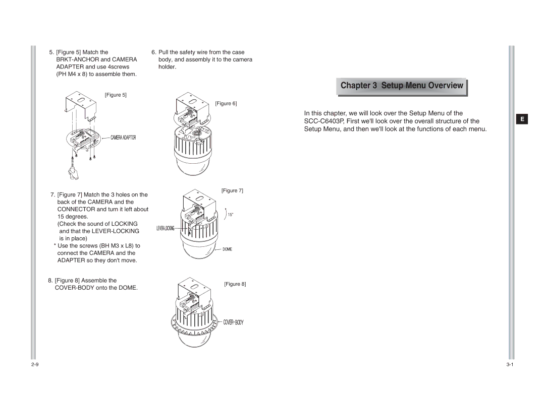
SCC-C6403P specifications
The Samsung SCC-C6403P is a high-performance CCTV camera designed to meet the surveillance needs of a variety of environments, including commercial spaces, residential areas, and industrial sites. This model is renowned for its exceptional image quality, robust construction, and advanced features that ensure reliable monitoring and security.One of the standout features of the SCC-C6403P is its superior image resolution. With a robust sensor that offers high-definition video capture, this camera provides clear and detailed images, even in low-light conditions. The integration of a 1/3" CCD sensor enhances the camera's capability to capture intricate details, which is vital for effective surveillance. This feature is particularly beneficial in scenarios requiring the identification of individuals or objects.
Another significant characteristic of the SCC-C6403P is its advanced low-light performance. Equipped with enhanced infrared capabilities, the camera can capture footage in complete darkness, offering peace of mind for users who require 24/7 monitoring. This is achieved through an automatic IR cut filter, which switches between day and night modes seamlessly, ensuring consistent performance despite varying light conditions.
The camera also boasts a robust housing design that is both weather-resistant and durable. With an IP66 rating, the SCC-C6403P can withstand harsh outdoor conditions, including heavy rain and dust infiltration. This durability makes it an ideal choice for a range of installations, from outdoor parking lots to indoor commercial facilities.
In terms of connectivity, the Samsung SCC-C6403P is equipped with versatile options to facilitate easy integration into existing surveillance systems. It supports various connection protocols and is compatible with several video management systems, providing flexibility and scalability for future expansions.
Furthermore, the camera features advanced motion detection technology, allowing it to differentiate between human movement and other forms of motion. This capability significantly reduces false alarms, ensuring that users are alerted only to genuine security threats.
In conclusion, the Samsung SCC-C6403P is a robust surveillance solution that combines high-definition video, advanced low-light performance, and durable construction. Its versatile connectivity and intelligent features make it a reliable choice for businesses and homeowners alike, ensuring comprehensive security and peace of mind in any environment.

