3.3.4 Card Status Register
The Card Status Register (CSR) transmits the card's status information to the host. The CSR is defined in Section 4.10.1 in the SDA Physical Layer Specification, Version 2.00.
3.3.5 SD Status Register
The SD Status Register (SSR) contains status bits that are related to the SD Card proprietary features and may be used for future applications. The SD Status structure is described in Section 4.10.2 in the SDA Physical Layer Specification, Version 2.00.
3.3.6 Relative Card Address Register
The
3.3.7 Operation Conditions Register
The Operation Conditions Register (OCR) stores a card's VDD voltage profile. Refer to Section 5.1 of the SDA Physical Layer Specification, Version 2.00 for more information.
3.4 Bus Topology
The family of SanDisk SD products supports two communication protocols: SD and SPI. For more details, refer to Section 3.5 of the SDA Physical Layer Specification, Version 2.00. Section 6 of the specification contains a bus circuitry diagram for reference.
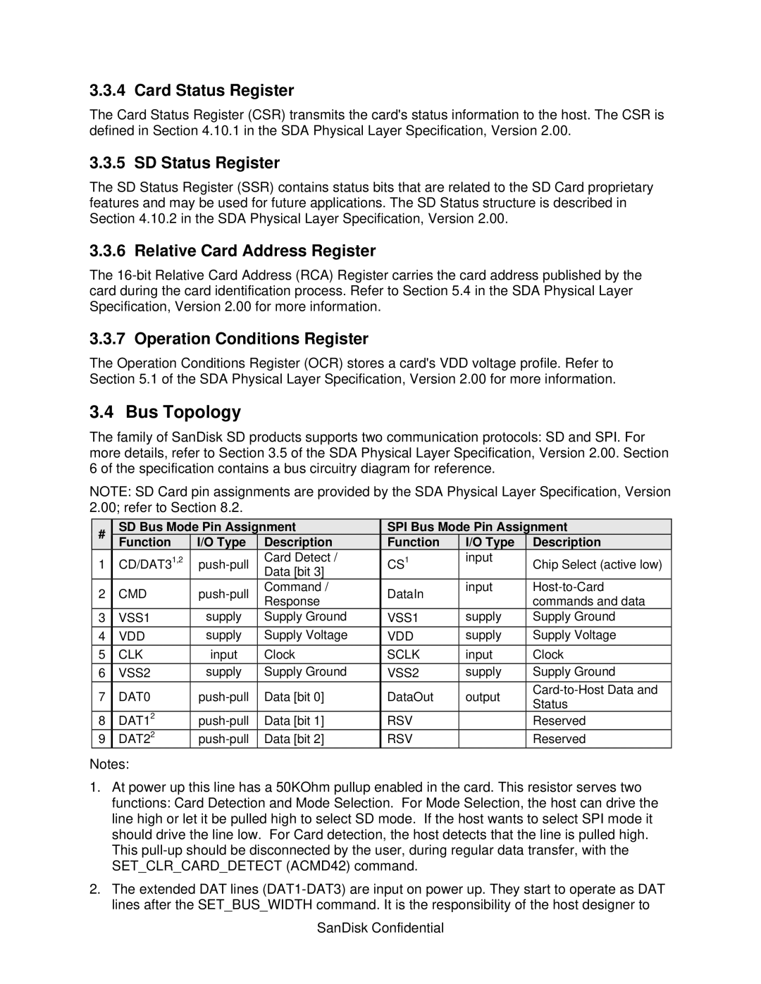
NOTE: SD Card pin assignments are provided by the SDA Physical Layer Specification, Version 2.00; refer to Section 8.2.
| # |
|
| SD Bus Mode Pin Assignment |
|
| SPI Bus Mode Pin Assignment | |||||||||||
|
|
| Function |
|
| I/O Type |
|
| Description |
|
| Function |
|
| I/O Type |
| Description | |
|
|
|
|
|
|
|
|
|
|
|
|
| ||||||
1 |
| CD/DAT31,2 |
|
| Card Detect / |
|
| CS1 |
| input |
| Chip Select (active low) | ||||||
|
|
|
|
|
|
|
|
|
| Data [bit 3] |
|
|
|
|
|
|
| |
2 |
| CMD |
|
| Command / |
| DataIn |
| input | |||||||||
|
|
| Response |
|
|
|
| commands and data | ||||||||||
|
|
|
|
|
|
|
|
|
|
|
|
|
|
|
| |||
3 | VSS1 |
| supply | Supply Ground |
| VSS1 |
| supply | Supply Ground | |||||||||
4 |
| VDD |
| supply | Supply Voltage |
| VDD |
| supply | Supply Voltage | ||||||||
5 |
| CLK |
| input |
| Clock | SCLK |
| input | Clock | ||||||||
6 | VSS2 |
| supply | Supply Ground |
| VSS2 |
| supply | Supply Ground | |||||||||
7 | DAT0 |
| Data [bit 0] | DataOut | output | |||||||||||||
| Status | |||||||||||||||||
|
|
|
|
|
|
|
|
|
|
|
|
|
|
|
|
|
| |
8 | DAT12 |
| Data [bit 1] | RSV |
|
|
| Reserved | ||||||||||
9 | DAT22 |
| Data [bit 2] | RSV |
|
|
| Reserved | ||||||||||
Notes:
1.At power up this line has a 50KOhm pullup enabled in the card. This resistor serves two functions: Card Detection and Mode Selection. For Mode Selection, the host can drive the line high or let it be pulled high to select SD mode. If the host wants to select SPI mode it should drive the line low. For Card detection, the host detects that the line is pulled high. This
2.The extended DAT lines