connect external pullup resistors to all data lines even if only DAT0 is to be used. Otherwise,
For more details regarding the SD Bus topology, refer to Section 3.5.1 of the SDA Physical Layer Specification, Version 2.00.
For more details regarding the SPI Bus topology, refer to Section 3.5.2 of the SDA Physical Layer Specification, Version 2.00.
3.5 Electrical Interface
The power scheme of SanDisk SD products is handled locally in each card and in the bus master. Refer to Section 6.4 of the SDA Physical Layer Specification, Version 2.00.
3.5.1 Power Up
Refer to Section 6.4.1 of the SDA Physical Layer Specification, Version 2.00, for information about power sequencing.
3.5.2 Bus Operating Conditions
SPI Mode bus operating conditions are identical to SD Card Bus Mode operating conditions. For details, see Section 6.6 of the SDA Physical Layer Specification, Version 2.00.
3.5.3 Bus Timing
SanDisk
3.6 Physical / Mechanical
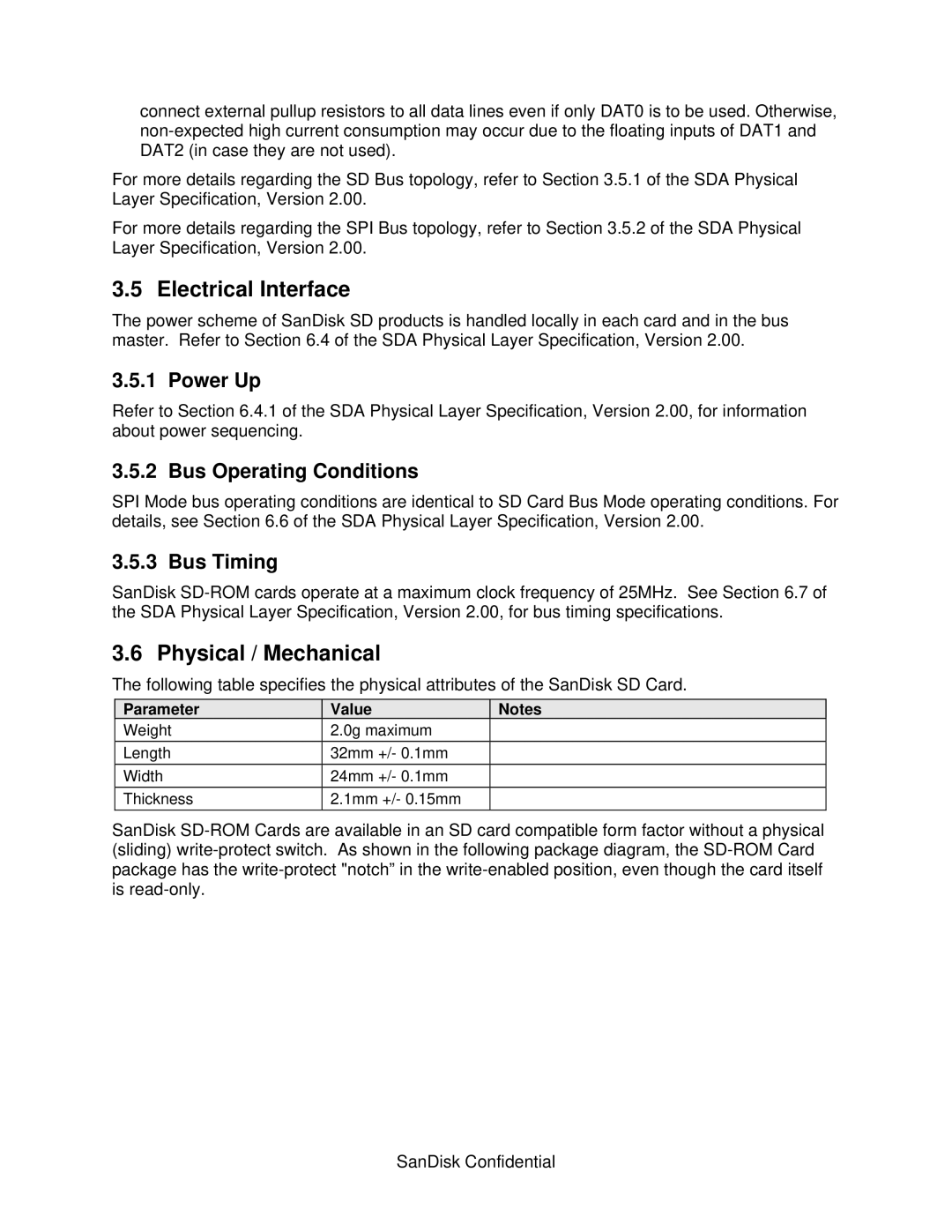
The following table specifies the physical attributes of the SanDisk SD Card.
Parameter | Value | Notes |
Weight | 2.0g maximum |
|
Length | 32mm +/- 0.1mm |
|
Width | 24mm +/- 0.1mm |
|
Thickness | 2.1mm +/- 0.15mm |
|
SanDisk