Diagram 2A
e, f
d ![]()
VESA on bac
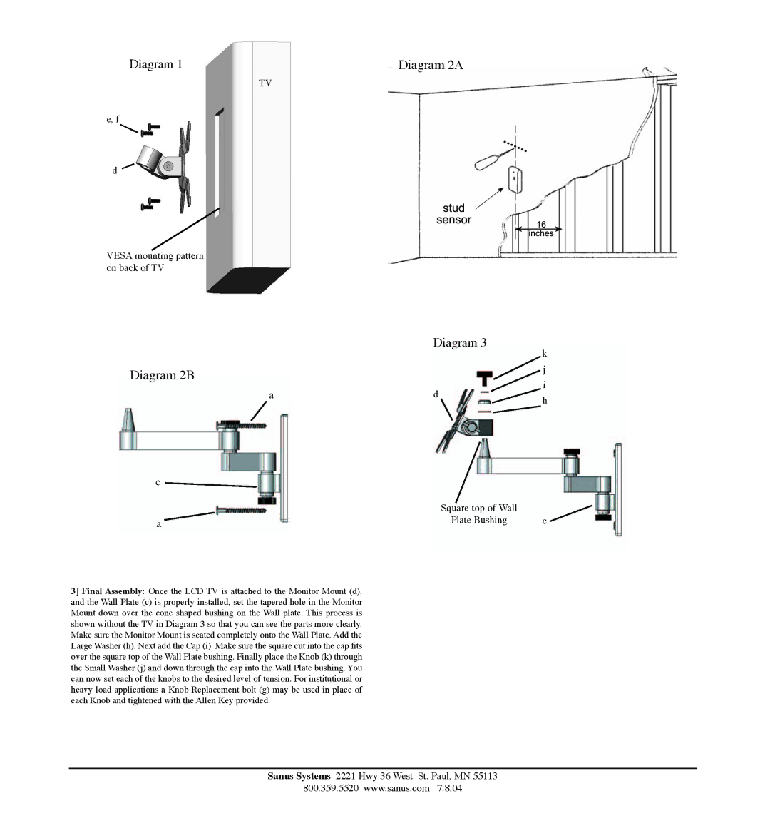
3] Final Assembly: Once the LCD TV is attached to the Monitor Mount (d), and the Wall Plate (c) is properly installed, set the tapered hole in the Monitor Mount down over the cone shaped bushing on the Wall plate. This process is shown without the TV in Diagram 3 so that you can see the parts more clearly. Make sure the Monitor Mount is seated completely onto the Wall Plate. Add the Large Washer (h). Next add the Cap (i). Make sure the square cut into the cap fits over the square top of the Wall Plate bushing. Finally place the Knob (k) through the Small Washer (j) and down through the cap into the Wall Plate bushing. You can now set each of the knobs to the desired level of tension. For institutional or heavy load applications a Knob Replacement bolt (g) may be used in place of each Knob and tightened with the Allen Key provided.
Sanus Systems 2221 Hwy 36 West. St. Paul, MN 55113
800.359.5520 www.sanus.com 7. 8.04