Setup (continued)
Remove the Stand
Cautions:
1. Carefully handle the unit during setup and consult authorized service personnel to ensure successful installation.
2. Before performing work spread cushioning over the base area to lay the Display on. This will prevent it from
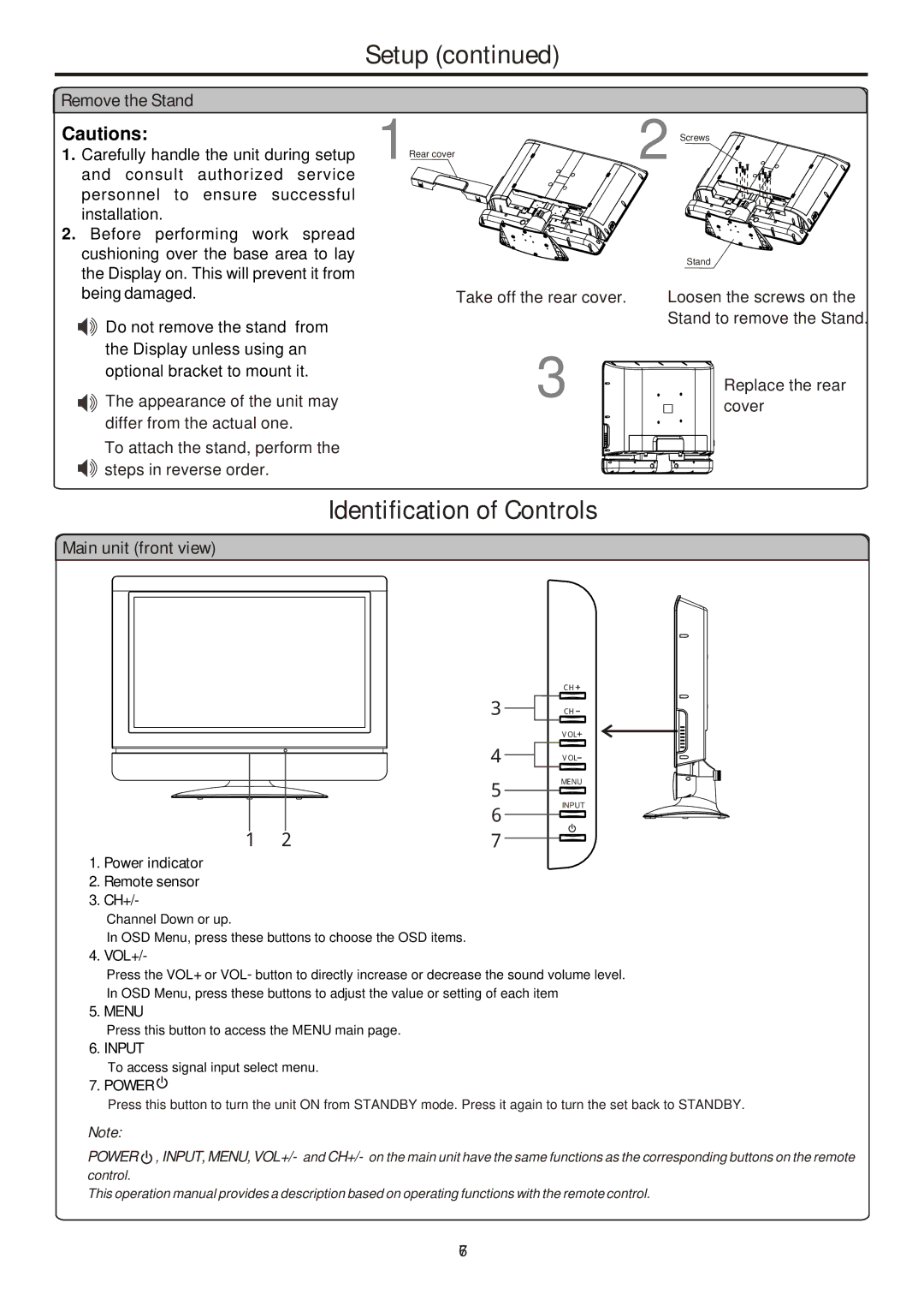
1 | Rear cover | 2 | Screws |
|
| ||
|
|
|
Stand
being damaged.
Do not remove the stand from the Display unless using an optional bracket to mount it. The appearance of the unit may differ from the actual one.
To attach the stand, perform the ![]()
![]() steps in reverse order.
steps in reverse order.
Take off the rear cover.
3
Loosen the screws on the Stand to remove the Stand.
Replace the rear cover
Main unit (front view)
1. | Power indicator | 1 | 2 |
2. Remote sensor |
|
| |
3. | CH+/- |
|
|
| Channel Down or up. |
|
|
4. | In OSD Menu, press these buttons to choose the OSD items. | ||
VOL+/- |
|
| |
| Press the VOL+ or VOL- button to directly increase or decrease the sound volume level. | ||
| In OSD Menu, press these buttons to adjust the value or setting of each item | ||
5. MENU |
|
| |
6. | Press this button to access the MENU main page. | ||
INPUT |
|
| |
| To access signal input select menu. | ||
7. POWER |
|
| |
| Press this button to turn the unit ON from STANDBY mode. Press it again to turn the set back to STANDBY. | ||
Note:
POWER , INPUT, MENU, VOL+/- and CH+/- on the main unit have the same functions as the corresponding buttons on the remote control.
This operation manual provides a description based on operating functions with the remote control.
67