Sanyo Installation | Configuration and Connections |
|
|
|
|
5.The Sanyo PLC Comm Adapter
6.Plug the
______ Secure all of the connector screws.
7.Plug the (4 or 5) BNC connectors from one end of the
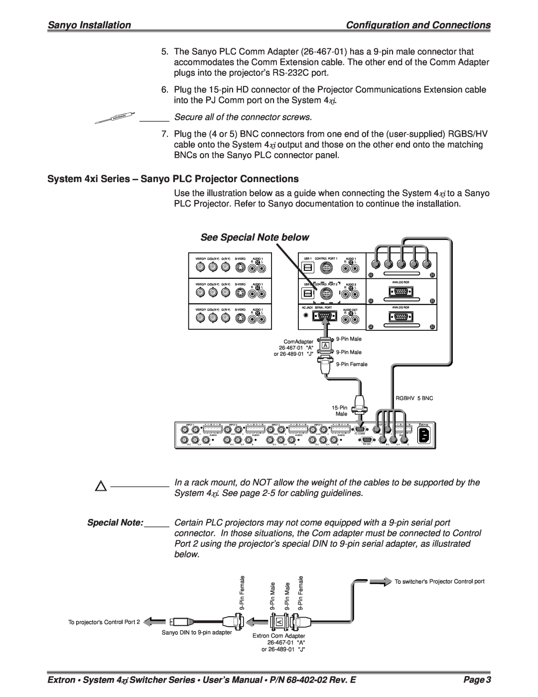
System 4xi Series – Sanyo PLC Projector Connections
Use the illustration below as a guide when connecting the System 4xi to a Sanyo
PLC Projector. Refer to Sanyo documentation to continue the installation.
See Special Note below
VIDEO/Y | AUDIO 1 | ||||
|
|
|
| R | L |
VIDEO/Y | AUDIO 1 | ||||
|
|
|
| R | L |
VIDEO/Y | AUDIO 1 | ||||
|
|
|
| R | L |
USB 1 | CONTROL PORT 1 |
| R | G | B | H | V |
AUDIO 1 |
|
|
|
| |||
|
| R | L |
|
|
|
|
USB 2 | CONTROL PORT 2 | AUDIO 2 |
| ANALOG RGB |
|
| |
|
|
|
| ||||
|
| R | L |
|
|
|
|
AC JACK | SERIAL PORT | AUDIO OUT |
| ANALOG RGB |
|
| |
|
|
|
|
|
| ||
|
| R | L |
|
|
|
|
ComAdapter ![]()
![]()
![]()
![]()
or ![]()
![]()
![]()
![]()
![]()
![]()
![]()
RGBHV 5 BNC
INPUT 1 | INPUT 2 | INPUT 3 | INPUT 4 | OUTPUT |
H/HV | V | AUDIO | H/HV | V | AUDIO | H/HV | V | AUDIO | H/HV | V | PJ COMM | H/HV |
|
|
|
|
|
|
|
| AUDIO |
|
V
AUDIO
R/C | G/Y | B | R/C | G/Y | B | R/C | G/Y | B | R/C | G/Y | B | RS 232 | R/C | G/Y | B |
____________ In a rack mount, do NOT allow the weight of the cables to be supported by the
System 4xi. See page
Special Note: _____ Certain PLC projectors may not come equipped with a
connector. In those situations, the Com adapter must be connected to Control Port 2 using the projector’s special DIN to
To projector's Control Port 2
Sanyo DIN to
To switcher's Projector Control port | |||
|
|
| |
| A |
|
|
Extron Com Adapter |
| ||
| |||
or | "J" |
| |
Extron • System 4xi Switcher Series • User’s Manual • P/N | Page 3 |