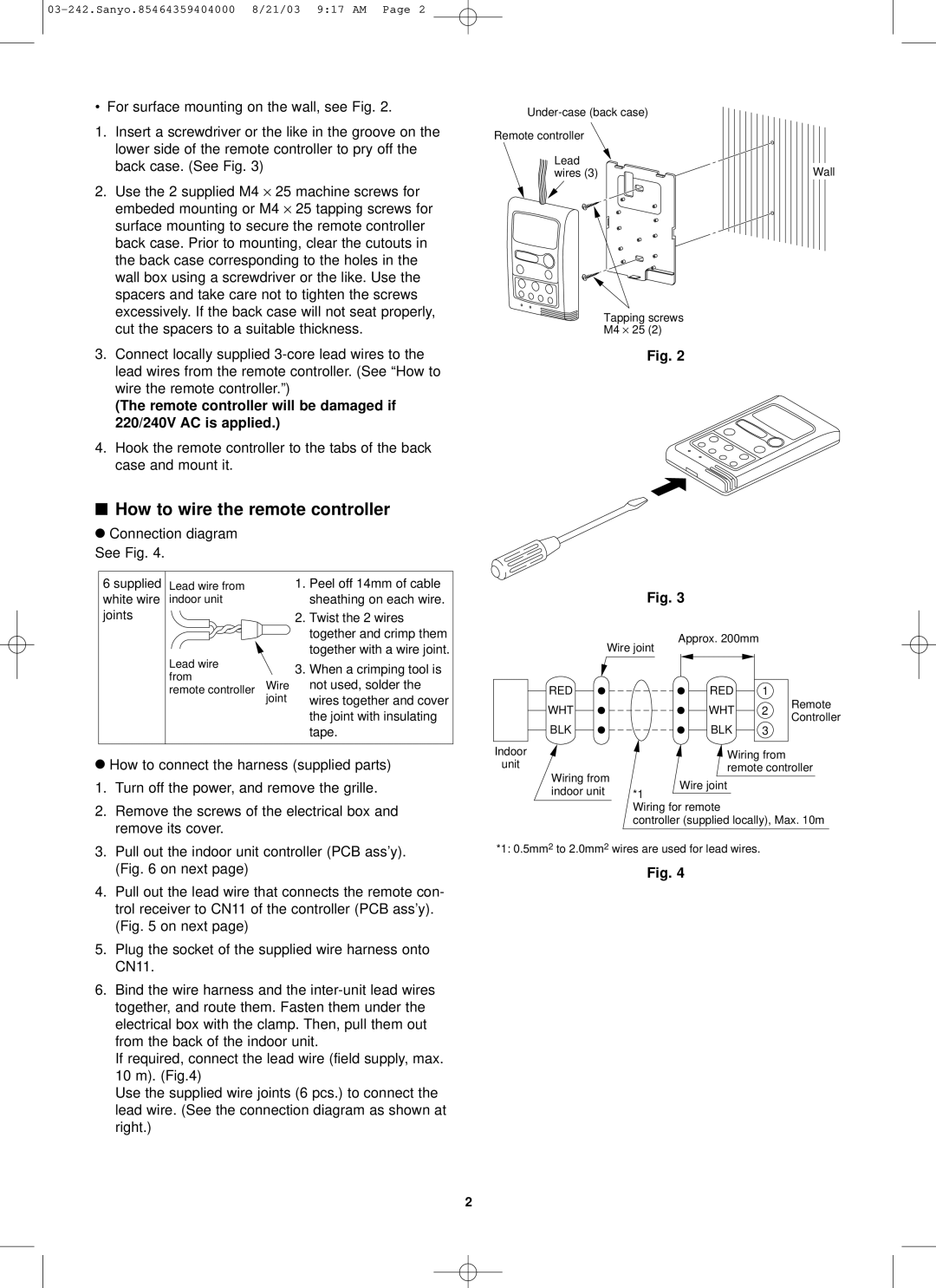
• For surface mounting on the wall, see Fig. 2.
1.Insert a screwdriver or the like in the groove on the lower side of the remote controller to pry off the back case. (See Fig. 3)
2.Use the 2 supplied M4 ⋅ 25 machine screws for embeded mounting or M4 ⋅ 25 tapping screws for surface mounting to secure the remote controller back case. Prior to mounting, clear the cutouts in the back case corresponding to the holes in the wall box using a screwdriver or the like. Use the spacers and take care not to tighten the screws excessively. If the back case will not seat properly, cut the spacers to a suitable thickness.
3.Connect locally supplied
(The remote controller will be damaged if 220/240V AC is applied.)
4.Hook the remote controller to the tabs of the back case and mount it.
■How to wire the remote controller
●Connection diagram See Fig. 4.
6 supplied | Lead wire from | 1. | Peel off 14mm of cable |
white wire | indoor unit |
| sheathing on each wire. |
joints |
| 2. | Twist the 2 wires |
|
|
| together and crimp them |
|
|
| together with a wire joint. |
| Lead wire | 3. | When a crimping tool is |
| from | ||
|
| not used, solder the | |
| remote controller Wire |
| |
| joint |
| wires together and cover |
the joint with insulating tape.
●How to connect the harness (supplied parts) 1. Turn off the power, and remove the grille.
2.Remove the screws of the electrical box and remove its cover.
3.Pull out the indoor unit controller (PCB ass’y). (Fig. 6 on next page)
4.Pull out the lead wire that connects the remote con- trol receiver to CN11 of the controller (PCB ass’y). (Fig. 5 on next page)
5.Plug the socket of the supplied wire harness onto CN11.
6.Bind the wire harness and the
If required, connect the lead wire (field supply, max. 10 m). (Fig.4)
Use the supplied wire joints (6 pcs.) to connect the lead wire. (See the connection diagram as shown at right.)
Remote controller
Lead | Wall |
wires (3) |
Tapping screws
M4 ⋅ 25 (2)
Fig. 2
Fig. 3
| Wire joint | Approx. 200mm |
|
| |
|
|
|
| ||
RED |
| RED | 1 |
| |
WHT |
| WHT | 2 | Remote | |
| Controller | ||||
BLK |
| BLK |
| ||
| 3 |
| |||
Indoor |
| Wiring from |
| ||
unit |
|
| |||
| remote controller | ||||
Wiring from | |||||
Wire joint |
|
| |||
indoor unit | *1 |
|
| ||
|
|
| |||
Wiring for remote
controller (supplied locally), Max. 10m
*1: 0.5mm2 to 2.0mm2 wires are used for lead wires.
Fig. 4
2