SPW-FTR124EH56 specifications
The Sanyo SPW-FTR124EH56 is a cutting-edge air conditioning unit that combines energy efficiency with advanced technology, making it ideal for both residential and commercial applications. As a part of Sanyo's renowned product line, this model stands out for its sleek design and innovative features, aimed at providing optimal comfort throughout the year.One of the key attributes of the SPW-FTR124EH56 is its inverter technology. This feature allows the compressor to adjust its speed dynamically, ensuring that the unit operates at the most efficient level for the given conditions. Consequently, this results in significant energy savings, with reduced power consumption compared to traditional air conditioning systems. The inverter technology also contributes to quieter operation, making it a perfect choice for living spaces, offices, and other environments where noise can be a concern.
The SPW-FTR124EH56 boasts a high cooling and heating capacity, making it versatile for varying climates. It is equipped with a powerful rotary compressor that ensures rapid temperature adjustment, providing relief during hot summer days and warmth during chilly winters. The unit's continuous heating capability allows it to maintain comfortable indoor temperatures even in extreme outdoor conditions.
Another notable feature is its advanced filtration system. The air conditioning unit comes with a built-in air purifying filter that effectively removes dust, allergens, and other airborne particles. This not only enhances indoor air quality but also contributes to the longevity of the unit by reducing the accumulation of dirt and debris.
The SPW-FTR124EH56 offers a user-friendly interface, with an intuitive remote control that allows for easy temperature adjustments and mode selections. Additionally, it features a programmable timer, enabling users to set the unit to operate at specific times, ensuring the space is always at a comfortable temperature without wasting energy when it’s unnecessary.
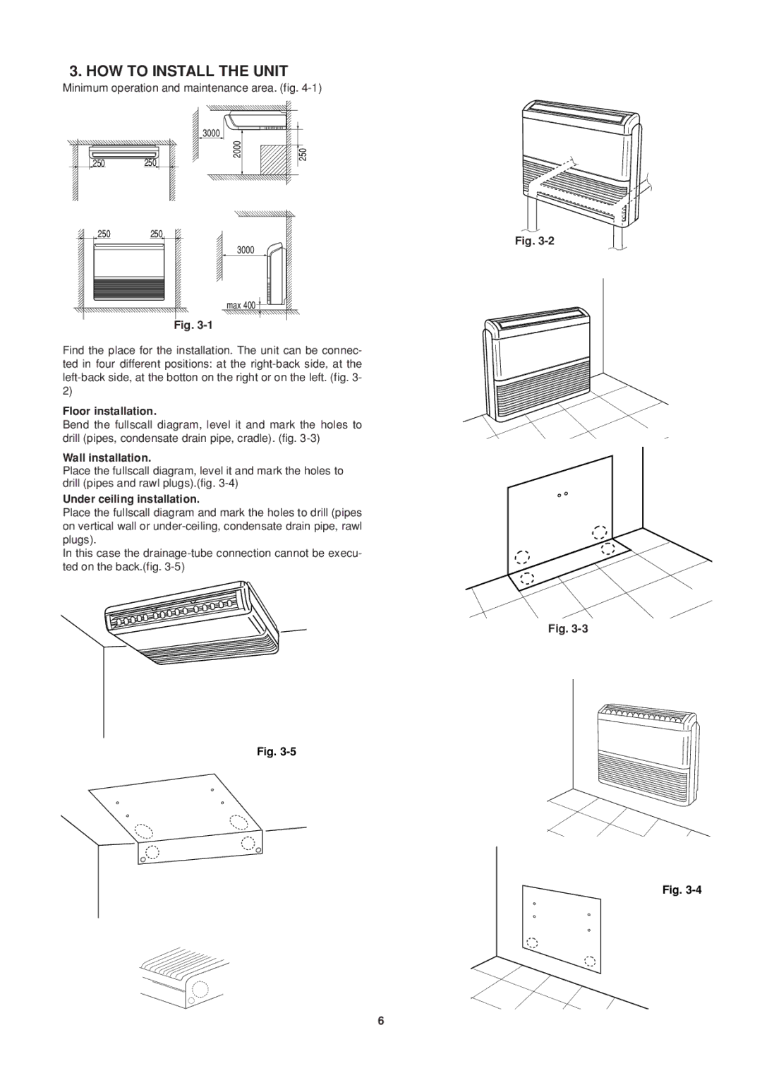
Moreover, the compact design of the Sanyo SPW-FTR124EH56 makes installation straightforward, allowing it to fit seamlessly into various settings. Its high energy efficiency rating highlights its environmental friendliness, appealing to eco-conscious consumers seeking sustainable climate control solutions.
In summary, the Sanyo SPW-FTR124EH56 is a highly efficient air conditioning unit that combines powerful performance with modern technology. With features like inverter technology, effective air filtration, and user-friendly controls, it is designed to provide year-round comfort while being mindful of energy consumption and environmental impact. Whether for home or office use, it represents an excellent choice for those seeking reliability and efficiency in climate control.

