SETTINGS
 External sync adjustment (VBS)
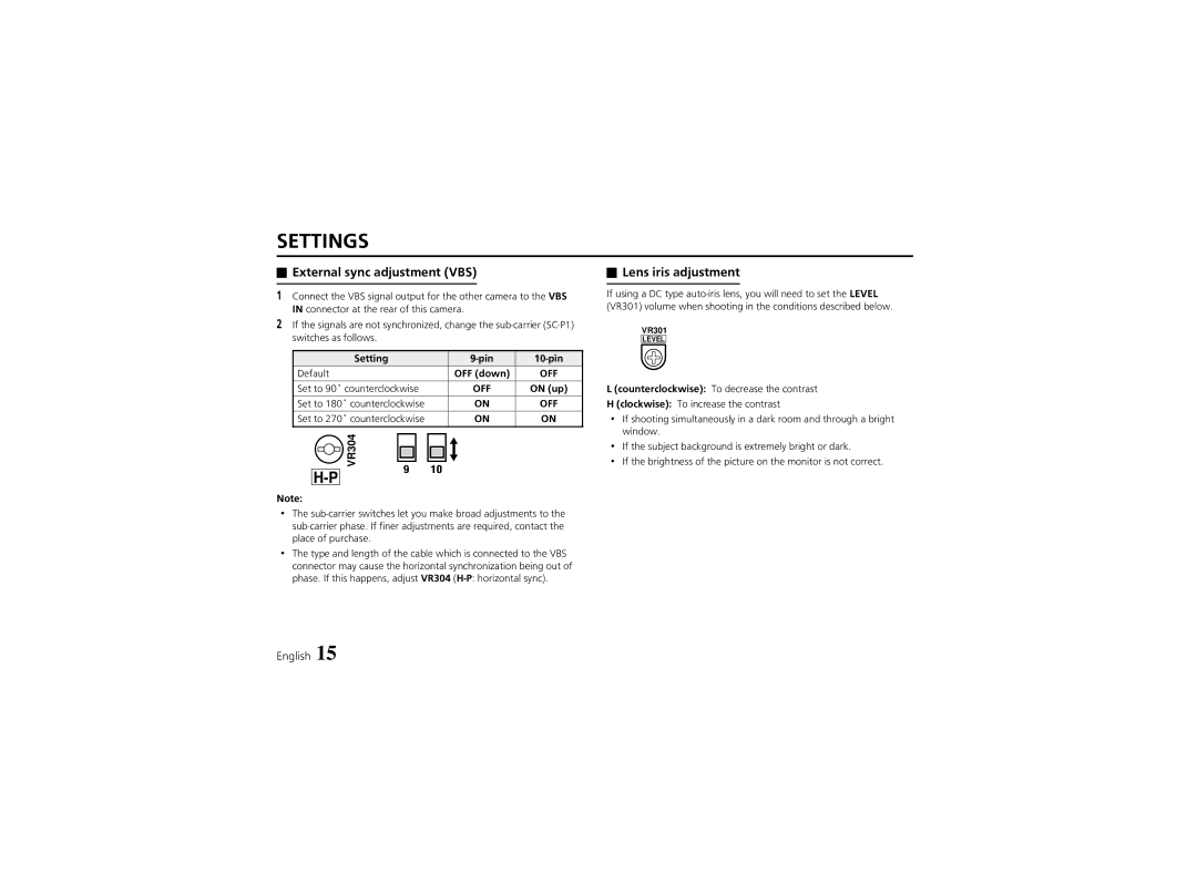
1Connect the VBS signal output for the other camera to the VBS IN connector at the rear of this camera.
2If the signals are not synchronized, change the
Setting | ||
Default | OFF (down) | OFF |
|
|
|
Set to 90˚ counterclockwise | OFF | ON (up) |
Set to 180˚ counterclockwise | ON | OFF |
|
|
|
Set to 270˚ counterclockwise | ON | ON |
|
|
|
 Lens iris adjustment
If using a DC type
VR301
LEVEL
L (counterclockwise): To decrease the contrast
H (clockwise): To increase the contrast
• If shooting simultaneously in a dark room and through a bright |
window. |
Note:
VR304 | 9 | 10 |
|
• | If the subject background is extremely bright or dark. |
• | If the brightness of the picture on the monitor is not correct. |
•The
•The type and length of the cable which is connected to the VBS connector may cause the horizontal synchronization being out of phase. If this happens, adjust VR304
English 15
