Voice Communications
VDC-DPN9585P/VCC-PN9575P
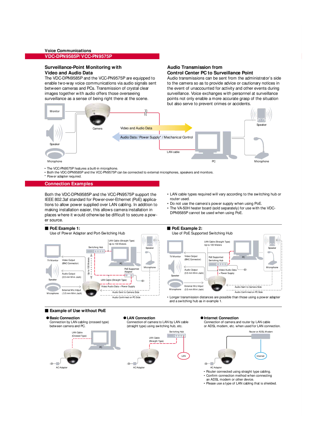
Surveillance-Point Monitoring with
Video and Audio Data
The
Monitor
Camera | Video and Audio Data |
Audio Transmission from
Control Center PC to Surveillance Point
Audio transmissions can be sent from the administrator’s side to the camera so as to provide advice or cautionary notices in the event of unaccounted for activity and other events during surveillance. Voice exchanges with personnel at surveillance points not only enable a more accurate grasp of the situation but also serve to prevent crimes or accidents.
Speaker
Audio Data / Power Supply* / Mechanical Control
Speaker
LAN cable
Microphone | PC | Microphone |
•The
•Both the
Connection Examples
Both the
•LAN cable types required will vary according to the switching hub or router used.
•Do not use the camera’s power supply when using PoE.
•The
![]() PoE Example 1:
PoE Example 1:
Use of Power Adapter and
![]() PoE Example 2:
PoE Example 2:
Use of PoE Supported Switching Hub
|
|
|
|
| LAN Cable (Straight Type) | ||
|
|
|
|
| Up to 100 Meters | ||
|
| Switching Hub |
| ||||
|
|
|
|
|
|
|
|
|
|
|
|
|
|
|
|
TV Monitor | (BNC Connector) | Meters |
|
| PC | ||
Video Output |
|
|
|
|
|
| |
|
| 100 |
|
| PoE Supported | ||
|
| to |
|
| |||
|
|
|
| Adapter | |||
| Audio Output | Up |
|
| |||
|
|
|
|
|
| ||
Speaker | (3.5 mm Mini Jack) |
|
|
|
|
|
|
| LAN Cable (Straight Type) | ||||||
|
| ||||||
|
|
|
|
| |||
|
|
| Video/Audio Data + Power Supply | ||||
Microphone | External Mic Intput |
|
|
| Audio Sent to Camera Side | ||
( 3.5 mm Mini Jack) |
|
|
| ||||
|
|
|
|
|
| ||
Speaker |
|
TV Monitor | Video Output |
| (BNC Connector) |
Microphone | Audio Output |
| |
Speaker | (3.5 mm Mini Jack) |
| |
Microphone | External Mic Intput |
(3.5 mm Mini Jack) |
LAN Cable (Straight Type) Up to 100 Meters
Speaker
PoE Supported | PC |
Switching Hub |
|
Microphone
Video/Audio Data
+ Power Supply
Audio Sent to Camera Side
Audio Confirmed on PC Side
Audio Confirmed on PC Side
•Longer transmission distances are possible than those using a power adapter and a switching hub as in example 1.
 Example of Use without PoE
Basic Connection | LAN Connection | Internet Connection |
Connection by LAN cabling (crossed type) between camera and PC.
Connection of camera to LAN by LAN cable | Connection of camera and router by LAN cable |
(straight type) using switching hub, etc. | or ADSL modem, etc. when used for LAN connection. |
LAN Cable | Switching Hub | Router or ADSL Modem |
(Crossed Type) | LAN Cable |
|
|
| |
| (Straight Type) |
|
| PC |
|
| LAN | Internet |
AC Adapter | AC Adapter | AC Adapter |
• Router connected using straight type cabling.
• Confirm connection method when connecting an ADSL modem or other device.
• Please use a type of LAN cabling that is shielded.