This explains how to check levels of DC power supply, I- mark sensor and gap sensor. Ensure that printer power is off. Remove the LH cover and then perform the following steps.
Additional equipment required
TP Test Module
Digital Multimeter
STEPS
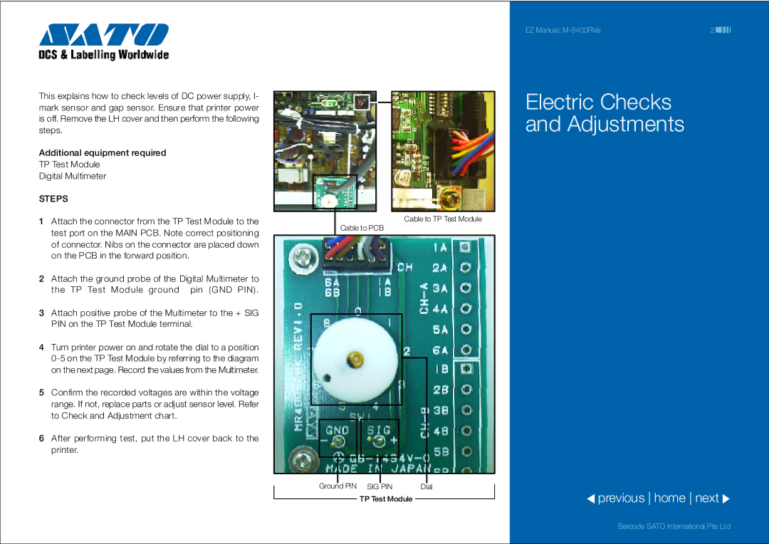
1Attach the connector from the TP Test Module to the test port on the MAIN PCB. Note correct positioning of connector. Nibs on the connector are placed down on the PCB in the forward position.
2Attach the ground probe of the Digital Multimeter to
the TP Test Module ground pin (GND PIN).
3Attach positive probe of the Multimeter to the + SIG PIN on the TP Test Module terminal.
4Turn printer power on and rotate the dial to a position
5Confirm the recorded voltages are within the voltage range. If not, replace parts or adjust sensor level. Refer to Check and Adjustment chart.
6After performing test, put the LH cover back to the printer.
EZ Manual: | 2 |
Electric Checks
and Adjustments
Cable to TP Test Module
Cable to PCB
|
|
|
|
|
|
|
|
|
|
|
|
|
|
|
|
|
|
|
|
|
|
|
|
|
|
|
|
|
|
|
|
|
|
|
|
|
|
|
|
|
|
|
|
|
|
|
|
|
|
|
|
|
|
|
|
|
|
|
|
|
|
|
|
|
|
|
|
|
|
|
|
|
|
|
|
|
|
|
|
|
|
|
|
|
|
|
|
|
|
|
|
|
|
|
|
|
|
|
|
| Ground | PIN SIG PIN | Dial |
| previous home next | ||||||
|
| ||||||||||||
|
|
|
|
|
|
|
|
|
|
|
|
| |
|
|
|
|
| TP Test Module |
|
|
| |||||
|
|
|
|
|
|
|
| ||||||
Barcode SATO International Pte Ltd