2-11 Blower Cone Installation
Thread (1)
(2)
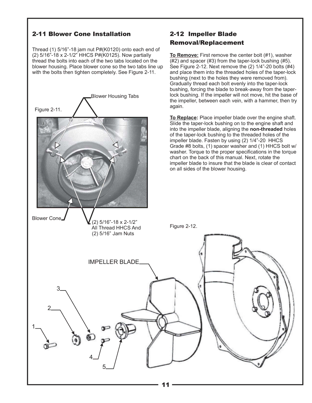
Blower Housing Tabs
Figure
Blower Cone
(2)
(2)5/16” Jam Nuts
2-12 Impeller Blade
Removal/Replacement
To Remove: First remove the center bolt (#1), washer (#2) and spacer (#3) from the
To Replace: Place impeller blade over the engine shaft. Slide the
Figure
IMPELLER BLADE
3
2
1
4
5
11