Scag Power Equipment 37621220 manual Length Of Hose Adjustment, Lower Hose To Boot Installation

Models: 37621219, 37621220 37621220

1 18
Download 18 pages 47.78 Kb
Page 12
Image 12
2-13 Length Of Hose Adjustment

2-13 Length Of Hose Adjustment

2-16 Lower Hose To Boot Installation

The hoses in steps 2-14 and 2-15 must be cut to fit your machine. Follow steps 2-14 and 2-15. Do not cut the hoses until you have tried to fit them on your machine. Remember that the hoses have to be long enough to allow for enough clamping surface between the inlet, blower assembly, and the deck boot, but have to remain short enough to prevent hose “kinks”.

Take the unattached end of the lower hose and slide it over the circular end of the boot. Use the lower hose clamp to secure the hose to the boot (Figure 2-16). Tip: Before securing clamp rotate hose counter-clockwise (away from yourself) approximately 1” to add in retaining boot to mower deck.

Figure 2-16.

2-14 Upper Hose Installation

Slide a 5”-6” upper hose clamp P#(J6011) onto both


ends of the 6” upper hose (Figure 2-15). Then slide one


end of the 6” hose onto the inlet. Make sure there is


about a two-inch overlap between the hose end and the


container inlet. Proceed to slide the opposite end of the


6” hose onto the outlet of the blower assembly. See


Figure 2-15 for details. Make sure both ends of the hose


are clearly attached to the inlet and the blower assembly

Lower Hose

Boot

inlet. Tighten the hose clamps.


Clamp


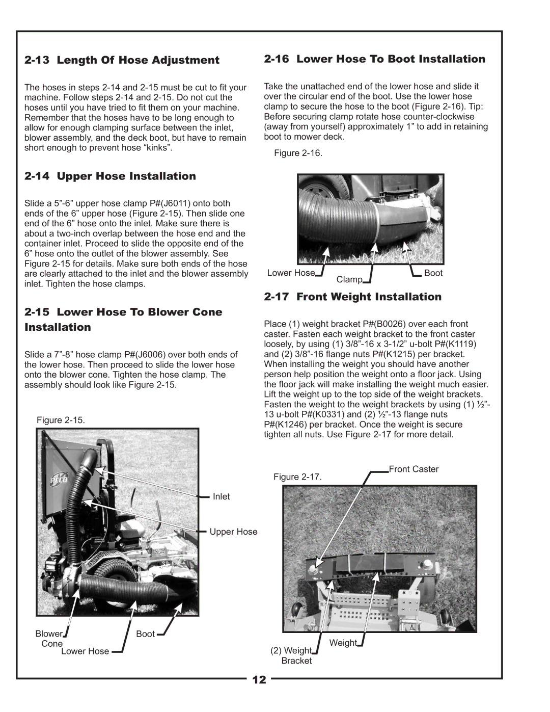
2-15 Lower Hose To Blower Cone Installation

Slide a 7”-8” hose clamp P#(J6006) over both ends of the lower hose. Then proceed to slide the lower hose onto the blower cone. Tighten the hose clamp. The assembly should look like Figure 2-15.

Figure 2-15.


Inlet


Upper Hose

Blower

Boot

Cone


Lower Hose


2-17 Front Weight Installation

Place (1) weight bracket P#(B0026) over each front caster. Fasten each weight bracket to the front caster loosely, by using (1) 3/8”-16 x 3-1/2” u-bolt P#(K1119) and (2) 3/8”-16 flange nuts P#(K1215) per bracket. When installing the weight you should have another person help position the weight onto a floor jack. Using the floor jack will make installing the weight much easier. Lift the weight up to the top side of the weight brackets. Fasten the weight to the weight brackets by using (1) ½”- 13 u-bolt P#(K0331) and (2) ½”-13 flange nuts P#(K1246) per bracket. Once the weight is secure tighten all nuts. Use Figure 2-17 for more detail.

Front Caster

Figure 2-17.

Weight

(2)Weight Bracket

12

Page 12
Image 12
Scag Power Equipment 37621220 manual Length Of Hose Adjustment, Lower Hose To Boot Installation, Upper Hose Installation